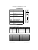
IRM3 SN RESET PWR MGMT CLN ON BOK RCV POK PWR A U I IRM3 INTELLIGENT REPEATER MODULE USER’S GUIDE ON LNK T X F O I R L R X U P S C O N S O L E ETHERNET
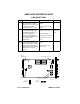
IRM3 QUICK REFERENCE CARD LED INDICATORS LED Description PWR IRM3 is receiving power from MMAC. BOK LED lit-Board is operating properly. IRM3 SN RESET LED not lit-Initialization problem. Press Reset switch. RCV IRM3 is repeating packet received from a connected segment. MGMT IRM3 is receiving/transmitting management packets. CLN Collision detected on a segment. POK Internal repeater port is OK. ON (AUI) AUI port is active repeater port. Fiber Optic port is active repeater port.
IRM3 QUICK REFERENCE CARD JUMPER SETTINGS Jumper H1 JP1 H6 and H8 Function Setting Default Enables/Disables Battery. When enabled, user-entered parameters are saved if power to the IRM3 fails. When disabled, parameters are lost. Enable: Jumper over pins 1 and 2 Makes IRM3 compatible with any THN-MIMs being used in the MMAC. This jumper is set for THN-MIMs with part numbers 9000043-06 and above and for THN-MIMs with part numbers below 9000043-06.
NOTICE Cabletron Systems reserves the right to make changes in specifications and other information contained in this document without prior notice. The reader should in all cases consult Cabletron Systems to determine whether any such changes have been made. The hardware, firmware, or software described in this manual is subject to change without notice.
Notice FCC NOTICE This device complies with Part 15 of the FCC rules. Operation is subject to the following two conditions: (1) this device may not cause harmful interference, and (2) this device must accept any interference received, including interference that may cause undesired operation. NOTE: This equipment has been tested and found to comply with the limits for a Class A digital device, pursuant to Part 15 of the FCC rules.
Notice CABLETRON SYSTEMS, INC. PROGRAM LICENSE AGREEMENT IMPORTANT: Before utilizing this product, carefully read this License Agreement. This document is an agreement between you, the end user, and Cabletron Systems, Inc. (“Cabletron”) that sets forth your rights and obligations with respect to the Cabletron software program (the “Program”) contained in this package. The Program may be contained in firmware, chips or other media.
Notice UNITED STATES GOVERNMENT RESTRICTED RIGHTS The enclosed product (a) was developed solely at private expense; (b) contains “restricted computer software” submitted with restricted rights in accordance with Section 52227-19 (a) through (d) of the Commercial Computer Software - Restricted Rights Clause and its successors, and (c) in all respects is proprietary data belonging to Cabletron and/or its suppliers.
CONTENTS CHAPTER 1 INTRODUCTION 1.1 Using This Manual....................................................................... 1-1 1.2 The Intelligent Repeater Module (IRM3) ..................................... 1-2 1.3 IRM3 Front Panel ........................................................................ 1-4 1.3.1 IRM3 Features ................................................................ 1-5 1.4 Repeater Functionality................................................................. 1-5 1.
Contents CHAPTER 4 LOCAL MANAGEMENT 4.1 Accessing Local Management Using a Terminal .........................4-3 4.1.1 Configuring a Local Management Terminal ....................4-3 4.1.2 Terminal Attachment Cable Configuration ......................4-4 4.1.3 Connecting the Terminal and Accessing Local Management4-5 4.2 Accessing Local Management Using a Modem ...........................4-7 4.2.1 Modem Configurations ....................................................4-7 4.2.
Contents CHAPTER 5 TROUBLESHOOTING 5.1 Using LANVIEW .......................................................................... 5-1 5.2 Troubleshooting Checklist ........................................................... 5-4 5.3 Using the Reset Switch ............................................................... 5-5 5.4 Before Calling Technical Support ................................................ 5-5 APPENDIX A SPECIFICATIONS A.1 Repeater Functionality.................................................
CHAPTER 1 INTRODUCTION Welcome to the Cabletron Systems Intelligent Repeater Module (IRM3) User’s Guide. This manual serves as an installation, management, and reference guide for the IRM3, and includes a description of the IRM3 capabilities and special features. The IRM3 provides a high performance IEEE 802.3 repeater with sophisticated network management capabilities for use in a Cabletron Systems Multi Media Access Center (MMAC). 1.
Chapter 1: Introduction Chapter 4, Local Management, describes Local Management (LM) and control capabilities for the IRM3. Local Management provides the tools to manage the IRM3 and its attached segments. Chapter 5, Troubleshooting, details the LANVIEW LEDs incorporated into the IRM3, which enable you to quickly diagnose any problems that may occur with the IRM3. This chapter also includes a troubleshooting checklist, procedures for using the reset switch and instructions for calling technical support.
The Intelligent Repeater Module (IRM3) .
Chapter 1: Introduction 1.3 IRM3 FRONT PANEL The IRM3 incorporates two ports that connect to external network segments: • One pair of IEEE 802.3 FOIRL fiber optic ports. The fiber optic ST port accommodates a wide variety of multimode fiber optic cable, including 50/125 µm, 62.5/125 µm, and 100/140 µm fiber optic cable, up to 2 km in length. • An IEEE 802.3 compliant AUI port.
Repeater Functionality The LANVIEW LEDs on the IRM3 indicate the following conditions: • The IRM3 is receiving power • An error has been detected with the IRM3 • The IRM3 is receiving packets from any segment connected to the MMAC • The IRM3 is detecting a collision from the network 1.3.1 IRM3 Features There are a number of features that provide for efficient use and maintenance of the IRM3. These features include the following: • Flash EPROM.
Chapter 1: Introduction data packets and regenerates the preamble of each data packet that enters the MMAC. In addition, IRM3 repeater functionality assures that problem segments connected to any port on the MMAC do not affect any other segments connected to the MMAC. If 32 consecutive collisions are detected on any segment, or if a collision detector is on for more than 2.4 ms, the IRM3 automatically partitions that segment.
Getting Help To help you see how your network is being used, and to help you plan for future network use, the IRM3 also provides Ethernet protocol counters on the port and board level for the following protocols: • • • • • • • • • AppleTalk Banyan Cabletron DECnet ISO/OSI Novell TCP/IP XNS Other For further specific information on in-band management of the IRM3, refer to the applicable Network Management Package User’s Manual. 1.
Chapter 1: Introduction Before calling Cabletron Systems Technical Support, be prepared to provide the following information: • A detailed description of the failure. • A description of any action already taken to resolve the problem (swapping the bad unit with a unit known to work properly, etc.) • A description of your network (environment, layout, cable type and length, etc.) • Serial numbers of all Cabletron Systems products used in the network.
Related Manuals 1.8 RELATED MANUALS The manuals listed below should be used to supplement the procedures and other technical data provided in this manual. The procedures will be referenced where appropriate, but will not be repeated. Cabletron Systems Multi Media Access Center Overview and Setup Guide. Cabletron Systems IRM3 Management Module Guide for Microsoft Windows.
CHAPTER 2 NETWORK PLANNING AND CONFIGURATION This chapter addresses some of the configuration issues that you should consider when installing the IRM3, including 802.3 standards related to repeaters, transceivers, and cables. This chapter also gives an overview of Cabletron Systems Multi Media Access Center (MMAC) and the Media Interface Modules (MIM) that can be managed by the IRM3. Finally, an example of a network configuration using the IRM3 is provided. 2.
Chapter 2: Network Planning and Configuration When connecting a network segment to the IRM3 through a transceiver and an AUI cable, the following requirements must be met: • The transceiver to which the IRM3 will be connected must meet Ethernet Version 1, Version 2 or IEEE 802.3 standards. • The AUI cables connecting the IRM3 to the transceiver on the network must be IEEE 802.3 type cables and must not exceed 50 meters in length.
The IRM3 in the Multi Media Access Center • Budget and Propagation Delay - When determining the maximum fiber optic cable length, the fiber optic budget delay and total network propagation should be calculated and taken into consideration before fiber runs are incorporated in any network design. Fiber optic budget is the combination of the optical loss due to the fiber optic cable, in-line splices, and fiber optic connectors.
Chapter 2: Network Planning and Configuration 2.2.1 Media Interface Modules The following is a description of the types of Cabletron Systems MIMs that can be installed in the MMAC and managed by the IRM3. THN-MIM Thin Coaxial Module The THN-MIM has 12 Ethernet/IEEE 802.3 compliant attachments to either thin or thick coaxial cable through a thick-to-thin adapter. The thin coaxial segment, which may be up to 185 meters in length, can accommodate up to 29 connections per segment.
Sample Network Configuration TRMIM Token Ring Modules Cabletron Systems TRMIM Token Ring modules are available with 12 or 24 ports equipped with either RJ45 or DB9 connectors. Token Ring modules that support unshielded twisted pair (UTP) cable provide for segments of up to 100 meters. With modules that support shielded twisted pair (STP) cable, you can attach segments of up to 200 meters. 2.
CHAPTER 3 INSTALLING THE IRM3 This chapter provides the instructions needed to install and verify the proper operation of the IRM3 into a network. The information in this chapter pre-supposes that the previous sections have been completed properly.
Chapter 3: Installing the IRM3 3.2 SETTING THE IRM3 JUMPERS There are eight jumpers on the IRM3 as shown in Figure 3-1. Four of the jumpers, H1, H6, H8, and JP1 can be changed. The remaining jumpers are for Cabletron Systems use only and should not be changed from their default positions. 3.2.1 Setting the Battery Enable/Disable Jumper (H1) The Battery Enable/Disable Jumper (H1, Figure 3-1) allows you to enable or disable the Battery Back-up for RAM on the IRM3.
Setting the IRM3 Jumpers Battery Enable/Disable For Cabletron Use Only H1 H2 H4 H3 H5 JP1 H8 H6 CTS-Modem Port CTS-Console Port THN-MIM Jumper 0494104 1 H1/JP1 Pin Numbers 2 3 Figure 3-1 H6/H8 Pin Numbers 1 2 3 IRM3 Jumper Locations 3.2.2 Setting the CTS External/Internal Jumper (H6, H8) The IRM3 UPS port and CONSOLE port are RS232 interfaces that use Request to Send (RTS), Clear to Send (CTS), and Data Terminal Ready (DTR) to control data flow.
Chapter 3: Installing the IRM3 Set the CTS External/Internal Jumper as follows: • If RTS or DTR is generated by your device to the IRM3, place the jumper over pins 2 and 3. This is the position in which the IRM3 is shipped. • If RTS or DTR must be generated internally by the IRM3, place the jumper over pins 1 and 2. 3.2.3 Setting the THN-MIM Jumper (JP1) The THN-MIM Jumper (JP1, Figure 3-1) may need to be set depending on the revision level of the THN-MIMs installed in your MMAC.
Installing the IRM3 into an MMAC Chassis IRM-3 MMAC-8 KNURLED KNOBS BOARD SLOT 1 Figure 3-2 0494105 IRM3 Installation 3. Secure the module to the MMAC by turning the knurled knobs. Be sure that the module is firmly attached to the MMAC. Failure to do so may result in improper operation. WARNING Fill all open slots in the MMAC hub with blank plates. If the plates are not installed, the MMAC may fail to comply with allowed limits of conducted and radiated emissions. 4. Power on the MMAC. 5.
Chapter 3: Installing the IRM3 IRM3 SN RESET SWITCH RESET PWR MGMT CLN BOK RCV POK ON PWR LANVIEW LEDS A U I ON LNK T X F O 0494106 Figure 3-3 NOTES LANVIEW LEDs When the IRM3 is first powered up, the AUI port acts as the repeater port and the Fiber ports are off. This configuration can be altered using IRM3 Local Management or network management tools so that the Fiber ports act as the repeater port and the AUI port is off.
Pre-installation Test 3.4 PRE-INSTALLATION TEST Before installing the IRM3 in a live network, test the module in a controlled situation to ensure that it is repeating packets. With the IRM3 installed in an MMAC hub with a Media Interface Module (MIM), this test can be performed with two workstations (Figure 3-1) by completing the following steps: 1. Install a Media Interface Module (TPMIM, FOMIM, THN-MIM, etc.) into the same MMAC chassis as the IRM3. 2.
Chapter 3: Installing the IRM3 MMAC 3/FNB with IRM3 and TPMIM TPT File Server Workstation Client Workstation Figure 3-4 0494109 Pre-installation Test 3.5 CONNECTING THE IRM3 TO THE NETWORK This section provides procedures for connecting the IRM3 to the network using the AUI port or the Fiber Optic ports.
Connecting the IRM3 to the Network 3.5.1 Connecting to the Network Through the AUI Port Connect to the network through the AUI port by performing the following steps: ! CAUT ION Be sure to disable the SQE test function on the transceiver you connect to the IRM3 AUI port. Failure to do so will result in improper operation of the IRM3. Refer to the applicable transceiver manual. 1. Attach an external transceiver to the segment to which the AUI port will be attached.
Chapter 3: Installing the IRM3 3.5.2 Connecting to the Network Through the Fiber Optic Port When connecting a fiber optic link segment to the IRM3 Fiber Optic ports, you must keep the following in mind: • ST connectors attach to ST ports much like BNC connectors attach to BNC ports. The connector is inserted into the port with the alignment slot on the connector inserted into the alignment key on the port. The connector is then turned clockwise to lock it down.
Connecting the IRM3 to the Network 4. At the other end of the fiber optic cable, attach the fiber labeled 1 to the transmit port of the device. 5. Attach the fiber labeled 2 to the receive port. ST Fiber Optic Ports T X R X Fiber 2 ST Connectors Fiber 1 Figure 3-6 0494108 Connecting to the Fiber Optic Ports 6. Check that the LNK LED for the fiber port on the IRM3 is lit (Figure 3-3). If the LED is not lit, perform each of the following steps until it is: a.
Chapter 3: Installing the IRM3 3.6 INSTALLATION CHECKOUT After the IRM3 is connected to the network, verify that packets can be passed between the two Ethernet network segments through the IRM3. As in the pre-installation checkout, use two workstations set up as file server and client. Keep the server workstation stationary in the wiring closet with the IRM3, and use the client workstation to move around to each node that is connected to the IRM3 (Figure 3-7).
Connecting to the UPS Through the Console Port MMAC 3/FNB with IRM3 and TPMIM TPT Office Locations File Server Workstation Client Workstation Figure 3-7 0494110 Installation Checkout 3.7 CONNECTING TO THE UPS THROUGH THE CONSOLE PORT If you are using an American Power Conversion CS-600R/CS-1250R series Uninterruptible Power Source (UPS), you can monitor and control the UPS through the IRM3, using SPECTRUM Element Manager for Windows.
CHAPTER 4 LOCAL MANAGEMENT The Cabletron Systems IRM3/LM provides unique management and control capabilities for the IRM3. With Local Management for the IRM3, you have the tools to manage the IRM3 and its attached segments. For example, you can enable and disable ports and set parameters such as the IP Address of your IRM3 or its current date and time. You can also use Local Management to view a full array of statistics to the port level.
Chapter 4: Local Management Figure 4-1 shows the IRM3/LM screen flow.
Accessing Local Management Using a Terminal 4.1 ACCESSING LOCAL MANAGEMENT USING A TERMINAL This section describes how to access local management using a terminal. Local Management for the IRM3 is accessed through a VT200 or VT300 series terminal, or terminals running emulation programs for these series terminals. The terminal or emulating terminal is attached to the 9-pin port labeled CONSOLE on the IRM3. 4.1.
Chapter 4: Local Management Table 4-1 Terminal Setup Parameters (Continued) Menu Communications Setup Keyboard Setup Function Selection Transmit Transmit = 9600 Receive Receive = Transmit XOFF any option Bits, Parity 8 Bits, No Parity Stop Bit 1 Stop Bit Local Echo No Local Echo Port DEC-423, Data Leads Only Transmit any option Auto Answerback No Auto Answerback Auto Repeat any option Keyclick any option Margin Bell Margin Bell Warning Bell Warning Bell Auto Answerback No Au
Accessing Local Management Using a Terminal Table 4-3 9-pin to 9-pin Pinouts 9-Pin Male Connector (IRM3 End) to 9-Pin Female Connector (Terminal End) Pin 3 (Receive) to Pin 3 (Transmit) Pin 2 (Transmit) to Pin 2 (Receive) Pin 5 (Ground) to Pin 5 (Ground) Pin 7 (Request to Send) to Pin 8 (Clear to Send) Pin 8 (Clear to Send) to Pin 7 (Request to Send) 4.1.
Chapter 4: Local Management 5. Press RETURN. The IRM3 SNMP Local Management introductory screen, shown in Figure 4-2, appears on the terminal. IRM3 SNMP LOCAL MANAGEMENT Cabletron Systems Incorporated P.O. Box 5005 Rochester NH, 03867-5005 U.S.A. (603) 332-9400 IRM3 SNMP Version 0.00.xx (C) Copyright Cabletron Systems Inc. 1992 MAIN 0494112 Figure 4-2 IRM3 SNMP Local Management Introductory Screen 6. Press RETURN. The Device/Board/Port Counters screen (Main), shown in Figure 4-4, appears.
Accessing Local Management Using a Modem 4.2 ACCESSING LOCAL MANAGEMENT USING A MODEM Local Management for the IRM3 is accessed through a Hayes, or Hayes Compatible Modem meeting the AT Command Set. The modem is attached to the 9-pin port labeled CONSOLE on the IRM3. 4.2.1 Modem Configurations The modem configuration must be set as follows so that the modem can communicate with the IRM3 Local Management. Refer to your modem manual for instructions on setting the modem.
Chapter 4: Local Management 4.2.3 Connecting the Modem and Accessing Management NOTE If the modem you are using does not generate a Clear to Send (CTS) signal, Request to Send (RTS) signal, or a Data Terminal Ready (DTR) signal, the CTS jumpers on the IRM3 must be set to compensate for these signals. Refer to Chapter 3 for information on setting the CTS jumper. To access Local Management, proceed as follows: 1. Plug the 9-pin end of the RS232 cable into the RS232 port labeled CONSOLE on the IRM3. 2.
The Password Screen 4.3 THE PASSWORD SCREEN When either the terminal or modem are properly connected to the IRM3, the Password screen shown in Figure 4-3 will appear. The Password screen is the first step in accessing the local management screens of the IRM3. Enter Password: 0494113 Figure 4-3 IRM3 Password Screen To access local management continue as follows: 1. Enter your password. (The default password is the RETURN key.
Chapter 4: Local Management 2. Press RETURN. The IRM3 SNMP Local Management introductory screen, shown in Figure 4-2, appears on the terminal. 3. Press RETURN. The Device/Board/Port Counters screen (Main), shown in Figure 4-4, appears. Refer to Section 4.4 for more information regarding this screen. Local Management for the IRM3 is now ready for operation. 4.
The Device/Board/Port Counters Screen The errors are further broken down into the following categories: • Out of Window Collisions • Runt Packets • No Resources Available • Frame Alignment Errors • CRC Errors • Giant Packets You can also perform the following functions: • Reset all counter information associated with the MMAC back to zero. • Enable and disable an individual board. • Enable and disable an individual port.
Chapter 4: Local Management 4.4.2 Device/Board/Port/Counters Screen Fields This section briefly describes the Device/Board/Port Counters screen fields. Counter information is displayed separately on the screen for the whole device (IRM3), the selected board, and the selected port. Bytes Received Displays the number of bytes received. Packets Displays the total number of packets received or transmitted. Errors Displays the number of errors detected.
The Device/Board/Port Counters Screen Frame Alignment Errors Displays the number of errors due to misaligned packets. CRC Errors Displays the number of packets with bad Cyclical Redundancy Checks (CRC) that have been received from the network. This error is caused by a network device interfering with the original size of the packet when it is transmitted or received. Giant Packets Displays the number of packets received whose size exceeded 1518 data bytes, not including preamble.
Chapter 4: Local Management 4.4.4 Using the Enable Board/Disable Board Options The Enable and Disable Board options allow you to enable or disable the board that is displaying statistics at the Device/Board/Port Counters screen. Enable or disable the Board as follows: 1. Using the arrow keys, highlight the ENABLE BOARD or DISABLE BOARD option at the bottom of the Device/Board/Port Counters screen. 2. Press RETURN. The Board is now Enabled or Disabled as selected. 4.4.
Community Names Screen COMMUNITY NAMES Select this option to designate community names for the devices attached to your IRM3. With these names, you can set the SNMP compliant network management workstations that will receive alarms from the IRM3. Community names authenticate an SNMP request, since the IRM3 only responds to a community name contained in the Community Name table. Additionally, the Community Names screen acts as a password screen.
Chapter 4: Local Management 4.5.1 Accessing the Community Names Screen To access the Community Names screen: 1. Using the arrow keys, highlight COMMUNITY NAMES at the bottom of the Device/Board/Port Counters screen (see Figure 4-4). 2. Press RETURN. The Community Names screen, Figure 4-5, appears. The following describes the Community Names screen. Each field is described, and instructions are given to set a Community Name.
Community Names Screen Access Indicates the access status of the workstations. The possible conditions are as follows: • RO (Read Only) These workstations have read only access to the IRM3. • RW (Read/Write) These workstations have read/write access. They can read and write to the IRM3, but they cannot change the IP address or the Community Names. • SU (Superuser) This is the Superuser workstation.
Chapter 4: Local Management 4. Press RETURN until the appropriate selection appears. The Access field is a toggle field that alternately displays RO, RW, SU, and NA when you press RETURN. 5. Using the arrow keys highlight the TRAPS field. 6. Press RETURN until the appropriate selection appears. The TRAPS field is a toggle field that alternately displays YES and NO when you press RETURN. YES indicates alarms from the IRM3 will be sent to the workstation.
The Setup Screen 4.6.1 Accessing the Setup Screen To access the IRM3 Setup option: 1. Using the right arrow key, highlight the SETUP option at the bottom of the Device/Board/Port Counters screen (see Figure 4-4). 2. Press RETURN. The Setup screen, Figure 4-6, appears. 11/15/91 SETUP 14:28:49 Device Name: Ethernet Address: 00-00-1d-00-39-14 IP Address: 134.141.52.48 IRM3 Set IP Address: 134.141.52.
Chapter 4: Local Management Ethernet Address Displays the Ethernet address of the IRM3 in a hexadecimal format (XX-XX-XX-XX-XX-XX). IP Address and Set IP Address Displays the current IP address of the IRM3. Set Current Date Displays the current date setting at the IRM3. Set Current Time Displays the current time setting (in 24 hour format) at the IRM3. Set Device Lock Displays the lock status of device. This can be set as either LOCKED or UNLOCKED.
The Setup Screen 4.6.4 Setting the Set Current Date Option To use the Set Current Date option, perform the following steps: 1. Using the arrow keys, highlight the Set Current Date field. 2. Enter the date into the field in a mm/dd/yy format. 3. Press RETURN. If an illegal date was entered in step 2, the error message “Illegal Information Entered” appears on the screen. 4. Using the arrow keys, highlight the SAVE SETUP option at the bottom of the Setup screen. 5. Press RETURN.
Chapter 4: Local Management 3. Using the arrow keys, highlight the SAVE SETUP option at the bottom of the Setup screen. 4. Press RETURN. The message “Modified screen Information Has Been Saved!” appears on the screen. NOTE If you have just unlocked the device, you must also reenable the boards. Refer to Section 4.4.4 for information on enabling/disabling boards. 4.6.7 Setting the Set Refresh Time Option To set the Set Refresh Time option perform the follosing steps: 1.
Port Association Screen PORT ASSOCIATION 11/15/91 14:26:43 Device Name: IRM3 Ethernet Address: 00-00-1d-00-39-14 IP Address: 134.141.52.48 AUI Port REPEATER, RETURN FIBER Port OFF SAVE ASSOCIATION 0494117 Figure 4-7 Port Association Screen 4.7.2 Port Association Screen Fields The following briefly explains each field on the Port Association screen. Date Displays the date to which the internal clock of the IRM3 is set.
Chapter 4: Local Management AUI Port, FIBER Port Displays the port association configuration the IRM3 is currently using. The available configurations are as follows: • REPEATER, OFF Indicates that the AUI port is acting as the repeater and the Fiber port is off. • OFF, REPEATER Indicates that the AUI port is off and the fiber port is acting as the repeater. 4.7.3 Changing the Port Association To change the Port Association, perform the following steps: 1.
The Token Ring Board Status Screen 4.8.1 Accessing the Token Ring Board Status Screen Access the IRM3 Token Ring Board Status Option as follows: 1. Using the arrow keys, highlight the Token Ring Board Status option on the Device/Board/Port Counters screen. NOTE If no Token Ring boards are installed, the option will be NO TOKEN RING BOARDS, and you will not be able to access the Token Ring Board Status screen. 2. Press RETURN. The Token Ring Board Status screen, Figure 4-8, appears.
Chapter 4: Local Management 4.8.2 Token Ring Board Status Screen Fields The following explains each field on the Token Ring Board Status screen. Date Displays the date to which the internal clock of the IRM3 is set. Time Displays the time, in a 24 hour format, to which the internal clock of the IRM3 is set. Device Name Displays the name assigned to the device. The default name is IRM3. Board Name Displays the name assigned to the Token Ring board. The default name is Board # (# = slot number).
The Token Ring Board Status Screen • INS (Inserted) Indicates that the station port is enabled and the attached station is operational (inserted into the ring). The station port must be enabled in order for the station to be inserted into the ring.
Chapter 4: Local Management Ring Port Status The Ring Port Status fields display only when you have a Token Ring concentrator module with externally accessible ring ports installed in the MMAC. These fields provide the Ring In (RI) and Ring Out (RO) conditions for the following: • STATUS Indicates the On or Off condition for the Ring In and Ring Out ports. • PHANTOM This field appears only with boards that support a phantom current. Indicates the status of the phantom current.
The Token Ring Board Status Screen • RIGHT...... ATTACHED Indicates the board is attached to the right FNB multiplexer. This indicates that the adjoining board has an open left FNB multiplexer (as long as both boards are set to the same ring speed, and are not in a bypass state). • RIGHT...... DETACHED Indicates that the board is disconnected from the right FNB multiplexer. This means it is also disconnected from all boards to its right in the MMAC. • RIGHT......
Chapter 4: Local Management Changing Station Port Status For Token Ring boards equipped with station ports, use the following option to change Station Port Status for any port on the board: 1. Using the arrow keys, highlight the STATION PORT X (X = port number) option. 2. Press the + key (press SHIFT and + keys) to increment the port number or the - key to decrement the port number. 3. When you have selected the port number, use the arrow keys to highlight either the ENABLE or DISABLE option. 4.
The Token Ring Board Status Screen Changing Ring Port Status The Ring Port Status option displays only when a Token Ring board with externally accessible ring ports is installed in the MMAC. The Ring Port Status option enables you to turn the Ring In and Ring Out ports on or off. Depending on the type of board you have installed, the phantom current and media type options may also display. 1. Use the arrow keys to highlight the RI or RO options for the Status field. 2.
Chapter 4: Local Management 5. Refer to the previous section for a description of the FNB status conditions. 6. Use the arrow keys to highlight the SAVE command and press RETURN. The message “Modified screen Information Has Been Saved!” appears on the screen. Changing the Board Speed Setting Token Ring boards can operate at 4 Mbps or 16 Mbps. To change the board speed setting, perform the following: 1. Use the arrow keys to highlight the SPEED option. 2.
CHAPTER 5 TROUBLESHOOTING This chapter includes information that will enable you to troubleshoot your IRM3 if a problem should occur. This chapter describes the LANVIEW LEDs on the IRM3, provides a troubleshooting checklist, and outlines the information you should have on hand if you need to call Cabletron Systems Technical Support. 5.1 USING LANVIEW The IRM3 uses Cabletron Systems built-in visual diagnostic and status monitoring system called LANVIEW.
Chapter 5: Troubleshooting Table 5-1 LANVIEW Troubleshooting LED COLOR DESCRIPTION PWR (Power) Green Indicates that the IRM3 is receiving power from the MMAC. ERROR CONDITION/RECOMMENDED ACTION If off, the IRM3 has lost power. Check the MMAC Power Supply. Ensure that the IRM3 is firmly installed and properly connected to the MMAC backplane. BOK Green (Board OK) Indicates that the board is operating properly. If off, there is an initialization problem with the board.
Using LANVIEW Table 5-1 LANVIEW Troubleshooting (Continued) LED COLOR DESCRIPTION CLN (Collision Present) Red When flashing, a collision is being detected on one or more segments connected to the MMAC. You should note that periodic flashing is normal. Excessive flashing or on solid indicates excessive collisions. When on, the AUI port is receiving power. If the AUI port is the selected repeater port and this LED is off, the port is not receiving power.
Chapter 5: Troubleshooting 5.2 TROUBLESHOOTING CHECKLIST If your IRM3 is not operating properly, the following checklist describes some of the problems that may occur with the IRM3 installed in an MMAC, possible causes for the problem, and suggestions for resolving the problem. Figure 5-1 shows the LED locations. Table 5-2 Troubleshooting Checklist Problem Possible Causes Recommended Action No LEDs on. Loss of power to the MMAC.
Using the Reset Switch 5.3 USING THE RESET SWITCH The IRM3 incorporates a recessed Reset switch, located above the LEDs. See Figure 5-1. This Reset switch initializes the IRM3 processor. This will not initialize the RAM where your network management parameters are stored. To use the Reset switch, use a small screw driver to press the switch in. When this is done, the IRM3 will initialize itself. 5.
APPENDIX A SPECIFICATIONS The operating specifications for Cabletron Systems IRM3 are included in this Appendix. Cabletron Systems reserves the right to change these specifications at any time without notice. A.1 REPEATER FUNCTIONALITY Delay Times (Port x In to Port x Out): Start of Packet: 1450 ns maximum. Collision to JAM: 1550 ns maximum. Preamble: Input: Minimum of 40 bits to a maximum of 64 bits required. Output: 64 bits minimum (last 2 bits are 1, 1).
Appendix A: Specifications A.2 AUI PORT Type: 15 position D type receptacle Connector Shell: Protective Ground Table A-1 AUI Port Connections Pin Signal Pin Signal Pin Signal 1 Logic Ref. 6 Power Return 11 Logic Ref. 2 Collision + 7 No Connection 12 Receive - 3 Transmit + 8 Logic Ref. 13 Power (+12Vdc) 4 Logic Ref. 9 Collision - 14 Logic Ref. 5 Receive + 10 Transmit - 15 No Connection A.
Console Port A.4 CONSOLE PORT Type: Standard 9-pin RS232 Port Table A-2 RS232 Port Pinouts Pin Signal Pin Signal 1 Carrier Detect (CD) 6 Receive Clock (RXCL) 2 Transmit (TXD) 7 Ready to Send (RTS) 3 Receive (RXD) 8 Clear to Send (CTS) 4 Data Terminal Ready (DTR) 9 Ring Indicator (RI) 5 Logic Reference A.
Appendix A: Specifications A.7 AGENCY APPROVALS SAFETY Designed in accordance with UL1950, CSA C22.2, N0. 950, EN60950, and IEC950. Emissions The IRM3 meets the emission requirements of FCC class A, EN55022 class A, and VCCI class I. NOTE It is the responsibility of the person who sells the system of which the IRM3 will be a part to ensure that the total system meets allowed limits of conducted and radiated emissions.
INDEX A Attenuation 2-2 AUI Port 4-24 AUI Port Requirements 2-1 AUTO 4-27 FNB Status 4-28 FOMIM 2-4 H Help 1-7 B I Battery Enable/Disable 3-2 Board Mode 4-27, 4-30 Board Settings 4-29 Board Speed 4-32 BYP 4-26 INS 4-27 IP Address 4-17, 4-20 IRM3 description 1-2 features 1-5 front panel 1-4 installation 3-1 installing into an MMAC 3-4 jumper locations 3-3 jumpers 3-2 locking 4-21 unpacking 3-1 C Cable length 2-3 Community Names 4-15 Community Names Screen accessing 4-16 editing 4-17 fields 4-16 CRC Er
Index MMAC 2-3 Modem configurations 4-7 connecting 4-8 MT8-MIM 2-4 N Network configurations 2-5 connecting to 3-8 management capabilities 1-6 requirements 2-1 O Out of Window Collisions 4-12 P Phantom 4-28 Port Admin. Status 4-13 Port Association 4-15 Port Association Screen accessing 4-22 fields 4-23 Port Seg.