RoamAbout Access Point User’s Guide 9032848
Notice Cabletron Systems reserves the right to make changes in specifications and other information contained in this document without prior notice. The reader should in all cases consult Cabletron Systems to determine whether any such changes have been made. The hardware, firmware, or software described in this manual is subject to change without notice.
Notice FCC Notice This device complies with Part 15 of the FCC rules. Operation is subject to the following two conditions: (1) this device may not cause harmful interference, and (2) this device must accept any interference received, including interference that may cause undesired operation. NOTE: This equipment has been tested and found to comply with the limits for a Class A digital device, pursuant to Part 15 of the FCC rules.
Notice Taiwanese Notice — Class A Computing Device: CE Notice — Class A Computing Device: Warning! This is a Class A product. In a domestic environment, this product may cause radio interference, in which case the user may be required to take adequate measures. Achtung! Dieses ist ein Gerät der Funkstörgrenzwertklasse A. In Wohnbereichen können bei Betrieb dieses Gerätes Rundfunkstörungen auftreten, in welchen Fällen der Benutzer für entsprechende Gegenmaßnahmen verantwortlich ist.
Notice Declaration of Conformity Addendum Application of Council Directive(s): 89/336/EEC 73/23/EEC Manufacturer’s Name: Cabletron Systems, Inc. Manufacturer’s Address: 35 Industrial Way PO Box 5005 Rochester, NH 03867 European Representative Name: Mr. J.
Notice Getting Help For additional support related to this device or document, contact Cabletron Systems using one of the following methods: World Wide Web http://www.cabletron.com http://www.cabletron.com/wireless Phone (603) 332-9400 Internet mail support@cabletron.com FTP ftp://ftp.cabletron.
Contents Preface Overview . . . . . . . . . . . . . . . . . . . . . . . . . . . . . . . . . . . . . . . . . . . . . . . . . . . . . . . . . . . . . . . . . . . . . ix Intended Audience . . . . . . . . . . . . . . . . . . . . . . . . . . . . . . . . . . . . . . . . . . . . . . . . . . . . . . . . . . . . . . ix Terminology. . . . . . . . . . . . . . . . . . . . . . . . . . . . . . . . . . . . . . . . . . . . . . . . . . . . . . . . . . . . . . . . . . . .x Conventions . . . . . . . . . . . . . . . . . . . .
3 Installing Your Access Point Overview . . . . . . . . . . . . . . . . . . . . . . . . . . . . . . . . . . . . . . . . . . . . . . . . . . . . . . . . . . . . . . . . . . . . 3-1 Installing the Network Adapter . . . . . . . . . . . . . . . . . . . . . . . . . . . . . . . . . . . . . . . . . . . . . . . . . . . 3-2 Installing the AP into a Standalone Configuration . . . . . . . . . . . . . . . . . . . . . . . . . . . . . . . . . . . . 3-4 Installing the AP into a MultiSwitch 900 or DEChub 90 . . . . . . . .
Preface Overview The RoamAbout Access Point™ is a 2-port transparent bridge that connects a wired Ethernet (ThinWire™ or 10BaseT) local area network (LAN) and a wireless LAN. The Personal Computer Memory Card International Association (PCMCIA) Type II interface in the Access Point supports the RoamAbout 802.11 PC Card Network Adapter™, a radio frequency device (also referred to herein as PC Card). This manual describes how to install and configure RoamAbout Access Point.
Terminology Terminology The following terms are used throughout this manual. You should be familiar with these terms before you continue. x Term Definition RoamAbout Access Point A 2-port transparent bridge that connects a wireless LAN to a wired Ethernet LAN. RoamAbout PC Card Network Adapter A PC Card network adapter, consisting of a radio module and a PC Card, that installs in a RoamAbout Access Point or laptop PC to provide wireless connectivity in a LAN environment.
Conventions Conventions This manual uses the following conventions: Convention Meaning Courier type This special type indicates system output or user input. [Return] Refers to a key on the keyboard. For example, [Return] is the Return key and [Tab] indicates the Tab key. Ctrl/X Hold down the Control key and simultaneously press the key specified by X. UPPERCASE Uppercase letters in command lines indicate keywords that must be entered. You can enter keywords in either uppercase or lowercase.
Associated Documents Associated Documents The following document is available to help you install, operate, and better understand your RoamAbout Access Point: RoamAbout IEEE DS/PC Card and ISA Adapter Card User’s Guide This manual explains how to install, configure, and troubleshoot the RoamAbout PC Card Network Adapter.
Chapter 1 Introducing RoamAbout Access Point Overview This chapter provides an overview of RoamAbout Access Point and its operation, and includes product specifications. The RoamAbout Access Point (also referred to in this manual as Access Point or AP) connects a wireless client or desktop PC to a wired Ethernet Local Area Network (LAN). An example of a wireless client is a portable PC, such as a laptop or notebook computer.
Summary of Access Point Features Summary of Access Point Features The Access Point operates at the Data Link layer of the Open System Interconnection (OSI) model. The Access Point has the following features: • RoamAbout Access Point Management Software • Wireless connectivity to your LAN using a RoamAbout 802.11 PC Card Network Adapter • Allows wireless clients to roam from one wireless LAN into another wireless LAN without losing connectivity • IEEE 802.
Summary of Access Point Features Figure 1-1: Front, Side, and Rear View of the Access Point™ 15 1 14 Acc 5 6 7 8 9 Poin t 1 16 Ro amAbout 2 3 4 ess 1 2 17 10 11 12 Height: 27.31 cm (10.75 in) Width: 3.18 cm (1.25 in) Depth: 13.3 cm (5.25 in) 13 18 LKG-8679-931-02 The module contains the following external parts, LEDs, connectors, ports, and controls: Item Name Description 1 Network Connector (BNC) Connects the module to a ThinWire network.
Summary of Access Point Features Item 3 Name Module OK LED Description Lights (green) when the module passes its power-up self-test. If the module fails the power-up self-test, the Module OK LED is off. If this LED is flashing, the Ethernet or wireless port (or both) has a fault, preventing connection to the network. 4 Wired LAN Activity LED Indicates the status of the wired Ethernet segment.
Summary of Access Point Features Item Name Description 8 Wireless LAN Activity LED Lights (green) when a PCMCIA network adapter is transmitting or receiving. Packets received and filtered are not shown. The average brightness of the LED indicates the level of activity on the wireless port. If the LED is flashing together with the Bridge State LED (6), the wireless port has a fault that prevents the AP from establishing a connection to the network.
Product Specifications Product Specifications This section describes the physical, electrical, and environmental specifications of the Access Point. Physical Specifications Table 1-1 lists the physical specifications of the Access Point. Table 1-1: Physical Specifications Parameter Value Value Width 3.18 cm (1.25 in) Height 27.31 cm (10.75 in) Depth 13.34 cm (5.25 in) Weight 0.68 kg (1.5 lb) Electrical Specifications Table 1-2 lists the electrical characteristics for the Access Point.
Product Specifications Environmental Specifications Table 1-3 lists the environmental specifications of the Access Point. Table 1-3: Environmental Specifications Parameter Description Operating Environment Temperature1 5°C to 50°C (41°F to 122°F) Maximum rate of change 20°C/h (36°F/h) Relative humidity 10% to 95% (noncondensing) Wet-bulb temperature 32°C (90°F) Altitude Sea level to 2.
Product Specifications Power Supply Specifications Table 1-4 lists the electrical specifications of the AP’s power supply. Table 1-4: Power Supply Specifications Parameter Value Input voltage 100 Vac to 240 Vac Current at 120 V 0.25 A Frequency 50 Hz to 60 Hz Power consumption 16 W Output voltage 5.1 Vdc Output current (maximum) 1.8 A Acoustical Specifications Table 1-5 lists the acoustical specifications of the AP.
Roaming Roaming The Access Point enables wireless clients to move from the coverage area of one AP into the coverage area of another AP while maintaining LAN connectivity. This capability is called roaming. Figure 1-2 illustrates a wireless client roaming from one AP coverage area to another.
Access Point Bridging Services Access Point Bridging Services The Access Point provides the following bridging services: • Store-and-forward capability The AP receives, checks, and transmits frames to other LANs, enabling the configuration of extended LANs. • Frame filtering based on address Using the address database and the source and destination addresses from incoming frames, the AP’s forwarding and translating process module isolates the traffic that should not be allowed on other LANs.
Configuring Your Access Point • Full Bridge mode When configured for Full Bridge mode, the AP learns addresses from both the wireless network and the wired Ethernet LAN. The AP filters packets based on their destination address and forwards all packets with unknown addresses. The default Aging Timer interval in Full Bridge mode is 2 minutes. • Workgroup Bridge mode When configured for Workgroup Bridge mode (the default operating mode), the AP learns addresses only from the wireless side of the network.
Managing Your Access Point with SNMP Managing Your Access Point with SNMP You can manage your Access Point using any SNMP-compliant Network Management Station (NMS). These NMS systems use the MIB objects to manage the system. The Access Point supports the following MIB objects: • MIB II (RFC–1213) • IETF Bridge MIB (RFC–1493) • Ethernet MIB (RFC–1398) • DEC ELAN Vendor MIB • HUB PCOM MIB • RoamAbout Access Point MIB • 802.
Chapter 2 Preparing for the Installation Overview This chapter describes the contents of the shipment, discusses site verification information, and provides instructions for connecting a RoamAbout PC Card Network Adapter to the Access Point (AP). NOTE A RoamAbout DS-type PC Card Network Adapter (also referred to as a network adapter) is used in the examples in this chapter. Refer to your network adapter documentation for specific instructions on installing and configuring the network adapter.
Reviewing the Site Preparation Checklist Reviewing the Site Preparation Checklist Before you unpack and install the AP, review the following checklist to ensure that all site preparation tasks were completed. General √ Determine where you will install the AP. Ideally, the AP should be located as high as possible. For more information, refer to Selecting the Location for the Access Point on page 2-5. √ Ensure that the Ethernet LAN is in place and operable.
Reviewing the Site Preparation Checklist Electrical and Environmental Requirements √ Ensure that the electrical and environmental requirements are within the ranges described in the Product Specifications section in Chapter 1. Cabling Requirements √ For standalone and DEChub 90 AP configurations: Ensure that you have two 9-pin DECconnect adapters (H8571–J) and an MMJ DECconnect BC16E cable for connecting the setup port device to the AP.
Unpacking and Checking the Contents of the Shipment Unpacking and Checking the Contents of the Shipment Unpack the unit and check the shipment for damage or missing parts. The shipment includes the following: • RoamAbout Access Point • Power supply (included only with the standalone version of the AP) • RoamAbout Access Point User’s Guide • RoamAbout Access Point Quick Start • RoamAbout Access Point Management Software (on floppy).
Selecting the Location for the Access Point Selecting the Location for the Access Point Before you install your Access Point, select the most appropriate location for the AP in your environment. You can install the AP in a MultiSwitch 900 or DEChub 90, or mount the AP on a wall, ceiling, or cubicle partition. Ideally, the AP should be located so that a clear line of sight exists between the radio module component of the AP’s network adapter and the radio modules on the wireless clients.
Selecting the Location for the Access Point Figure 2-1: Mounting the Access Point in a Central Location R o amAbout 1 2 LKG-8805-931-01 For some building designs, centralized mounting may not be practical. If permanent obstructions prevent you from centrally mounting the Access Point, mount it as high as possible.
Chapter 3 Installing Your Access Point Overview This chapter provides a step-by-step procedure to install the 802.11 RoamAbout PC Card Network Adapter (also referred to as a network adapter) and the Access Point. NOTE Before installing the AP, ensure that all the procedures in Chapter 2 are completed.
Installing the Network Adapter Installing the Network Adapter To install the network adapter, do the following: NOTE Do not try to insert or swap a PC Card in the AP if the AP power is on or the unit is installed into a MultiSwitch 900 or DEChub 90. Always unplug the AP from the power supply (or remove the AP from the MultiSwitch or DEChub) before inserting a PC Card. Step Action 1 Select the appropriate location for the installation of your AP.
Installing the Network Adapter Step Action 3 Complete the PC Card insertion: 4 • Gently push the PC Card into the slot until it is firmly seated. You will sense a slight resistance as you insert the PC card. • When properly inserted, the PC card protrudes approximately 1-1/2 inches from the AP. Connect the optional Range Extender Antenna to the PC Card. NOTE For additional information about your network adapter, refer to the documentation associated with the network adapter.
Installing the AP into a Standalone Configuration Installing the AP into a Standalone Configuration This section describes how to install the AP as a standalone module. Perform the following procedure to install the AP as a standalone module: Step Action 1 Select the appropriate location for the installation of your AP.
Installing the AP into a Standalone Configuration Step Action To connect to a 10BaseT Network –– Connect the 10BaseT cable to the 10BaseT Ethernet connector, as shown in Figure 3-3. Figure 3-3: Connecting to a 10BaseT Network Acc ess Poin t Ro amAbout 1 2 LKG-8686-931-01 3 Connect the other end of the ThinWire cable or 10BaseT cable to an active Ethernet outlet, such as a DECconnect faceplate or other appropriate network device.
Installing the AP into a Standalone Configuration Step Action 4 Connect a 9-pin serial cable to the AP’s 9-pin, D-Sub, PC-compatible serial port, as shown in Figure 3-4. Note: The pinouts for the AP’s local setup connector are listed in Appendix A. Figure 3-4: Connecting to the Setup Port Acc ess Poin t Ro amAbout 1 2 LKG-8804-931-01 5 Connect the AP’s power supply cable to the power connector on the back panel of the module, as shown in Figure 3-5.
Installing the AP into a Standalone Configuration Step Action 6 Connect the power supply to an AC outlet to turn on the AP.
Installing the AP into a MultiSwitch 900 or DEChub 90 Installing the AP into a MultiSwitch 900 or DEChub 90 This section describes how to install the unit in a MultiSwitch 900 or DEChub 90. Removing the Back Cover If there is a cover on the back of the AP, you must remove it before inserting the AP into the backplane.
Installing the AP into a MultiSwitch 900 or DEChub 90 Seating the Module in the MultiSwitch 900 or DEChub 90 The hot-swap feature allows you to install the module in the MultiSwitch 900 or DEChub 90 without turning off power. Seating the module initiates the power-up sequence. NOTE Do not try to insert a PC Card into the AP while the AP is powered on. Refer to Chapter 2 for instructions on how to insert the PC Card. Always remove the AP from the MultiSwitch 900 or DEChub 90 before swapping a PC Card.
Installing the AP into a MultiSwitch 900 or DEChub 90 Step Action 5 Secure the radio module to its mounting point, using the mounting material enclosed in the wireless network adapter kit. For information on how to secure and mount the RoamAbout PC Card Network Adapter, refer to the IEEE 802.11 PC/ISA Card User’s Guide. Figure 3-7: Installing into a MultiSwitch 900 or DEChub 90 Release Lever Hub Manager Clicks when Status Display MultiSwitch 900 Module is Seated.
Installing the AP into a MultiSwitch 900 or DEChub 90 Removing the Module from the MultiSwitch 900 or DEChub 90 Perform the following procedure to remove the unit: Step Action 1 Lift the release lever located on the top of the MultiSwitch 900 slot or the DEChub 90 slot, as illustrated in Figure 3-8. 2 Pivot the module back on its bottom mounting tab, and disengage the module from the backplane.
Verifying the Operation of Your Access Point Verifying the Operation of Your Access Point The Access Point runs a series of self-tests on power-up and reports status using its LEDs. When power-up begins, the following occurs: Stage Description 1 The firmware begins running diagnostics, initializes minimal hardware, then sequentially turns LEDs 2 through 6 on and off. 2 After LED 6 turns on and then turns off, the firmware completes its diagnostics and hardware initialization.
Verifying the Operation of Your Access Point Figure 3-9: Normal LED Pattern Access Point 1 2 3 R o amAbout 4 5 6 7 1 2 LKG-10067-931-01 Item 1 2 3 LED Name Power OK Module OK Wired LAN Operational State On = power is okay On = self-test passed OK Blinking = network connection 4 Bridge State On = lights after 30 seconds indicating that the AP is forwarding packets 5 AP Saturated Off 6 Wireless LAN Activity Blinking 7 PC Card Present On = PC Card is installed Installing Your Access Point 3
Setting the PC Card Parameters Setting the PC Card Parameters The AP us shipped with default values that allow wireless clients to connect with default settings. To change these parameters, use the local setup port, or the RoamAbout Access Point Manager described in Chapter 4. Chapter 4 also provides instructions for specifying the AP’s SNMP management parameters.
Chapter 4 Configuring Your Access Point Overview This chapter describes how to configure your Access Point locally from a setup port, or remotely from the RoamAbout Access Point Manager or from a Network Management Station (NMS). You can configure the Access Point (AP) in two ways: • Locally via the Access Point setup port utility Local setup port commands allow you to configure the AP using a setup port device (a terminal or personal computer running terminal emulation software).
Configuring the AP Using the RoamAbout Access Point Manager Configuring the AP Using the RoamAbout Access Point Manager The RoamAbout Access Point Manager provides easy setup and software management of RoamAbout wireless networks. This application can assist a user in two ways: as a setup/configuration tool for new RoamAbout Access Points, and as a management tool to assist the ongoing management and support of RoamAbout wireless networks.
Configuring the AP Using the RoamAbout Access Point Manager Installation and Setup To install the Roamabout Access Point Manager, install the floppy disk (disk 1 of 2) in the PC and run A:SETUP (this can be done from the Windows Explorer, DOS prompt or via the Start Bar Run option). This software can only be run on Windows 95, Windows 98 and Windows NT V4.0. This software can also be run on either a wired PC or a wireless PC.
Configuring the AP Using the RoamAbout Access Point Manager When you first establish communications with the AP, you will be prompted for some general information and then prompted for your wireless parameters. It is highly recommended that you change the ‘Wireless Network Name’ from the default. ALL APs and clients on the LAN must share the same ‘Wireless Network Name’. The figures below show the Wireless Network Name and the Station Name being changed.
Configuring the AP Using the RoamAbout Access Point Manager You can do one of three types of resets: • Reset with current defaults, after changing a parameters. • Reset with Factory Defaults, if you want to reset all parameters. Note: This also clears out the IP address. • Upgrade the Flash Memory, by selecting this option if a new version of the AP code becomes available. For minor software upgrades, all your prior changes are retained after an upgrade.
Configuring the AP Using the RoamAbout Access Point Manager Access Point Software (Flash) Upgrades The software running inside the Access Point can be easily upgraded. You should randomly check our www site (listed in the front of this manual) to see the latest information concerning new software releases, new features, and bug fixes. To load the Access Point with an upgraded version of the firmware, it is suggested that you copy the .
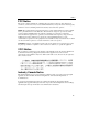
Configuring the Access Point Using the Setup Port Configuring the Access Point Using the Setup Port The setup port (on the MultiSwitch 900, or as a standalone) allows you to access and set Access Point parameters. This section describes how to access the module from either port and how to set those parameters. Examples of the actual setup screen displays are provided in this section to aid in the description of the setup port and to display the options that are available.
Configuring the Access Point Using the Setup Port Table 4-1: Setup Port Cabling Connecting to a... If the setup port device is a... Then use this cable... With these adapters... Standalone PC with a 9-pin DSub communications port and terminal emulation BC16E-xx1 or any std. PC compatible 9pin serial cable.
Configuring the Access Point Using the Setup Port Figure 4-1: Setup Port Cabling 3 3 1 int ss Po Acce 2 R oa mAbout H8571-J H8571-J 1 2 H8575-A BN24H H8575-A BC16E Item Description 1 MultiSwitch 900 setup port 2 Access Point setup port 3 Setup port device Configuring Your Access Point 4-9
Using the Access Point Setup Port Using the Access Point Setup Port After you have completed the setup port cabling, perform the following steps to access the Access Point Installation Menu. Step 1 Action Press Return on the setup port device a few times until a menu appears. If the AP is connected to a DEChub 90 or is a standalone unit, the Access Point Installation Menu appears. Go to the Access Point Installation Menu section.
Access Point Installation Menu Access Point Installation Menu The Access Point Installation menu allows you to set parameters when the AP is initially installed. NOTE When installing the AP into a DEChub 90, you must connect the setup port device to the setup port before applying power to the AP.
Access Point Installation Menu Description of Access Point Installation Menu Options This section describes the options that are available from the Access Point Installation Menu. RoamAbout Access Point INSTALLATION MENU [1] Reset with Factory Defaults This option reboots the AP, causing the module’s configured NVRAM parameters to be initialized to factory default values. NOTE This action deletes all configuration settings and replaces them with factory default values.
Access Point Installation Menu RoamAbout Access Point INSTALLATION MENU [2] Reset with Current Settings This option reboots the AP but leaves the module’s configured NVRAM parameters at their current settings. NOTE Allow approximately 1 minute for the module to reset and complete its self-test. The following example shows the dialog associated with this option.
Access Point Installation Menu RoamAbout Access Point INSTALLATION MENU [3] Show Current Settings This option shows the AP’s current settings. NOTE If the module is being configured for the first time, some fields are blank. The following example shows the dialog associated with this option.
Access Point Installation Menu RoamAbout Access Point INSTALLATION MENU [4] Set SNMP Read/Write Community If you want to perform SNMP management on the AP, you must assign it a community name. The format for a community name is a string consisting of 4 to 31 printable ASCII characters. This community name can be used by SNMP managers for read/ write access control. The default community name is public. In the following example, the string Accounting is entered as the AP’s SNMP read/ write community name.
Access Point Installation Menu RoamAbout Access Point INSTALLATION MENU [5] Add SNMP Trap Addresses This option prompts you to enter IP addresses to which SNMP traps are sent from the Access Point. A trap is a defined event or condition detected by the Access Point SNMP agent. The following example shows the dialog associated with this option.
Access Point Installation Menu RoamAbout Access Point INSTALLATION MENU [6] Delete SNMP Trap Addresses This option prompts you to select SNMP trap addresses for deletion. The following example shows the dialog associated with this option. ================================================================ DELETE SNMP TRAP ADDRESSES Format: The standard 4 octet dotted decimal notation in which each octet of the address is represented as a decimal value, separated by a ’.’ character. example: 16.20.40.
Access Point Installation Menu RoamAbout Access Point INSTALLATION MENU [7] Dump Error Log This option displays error log dumps used by support personnel when analyzing system faults. Up to four error log dumps can be stored, and the most recent dump is displayed first. The following example shows the dialog associated with this option.
Access Point Installation Menu RoamAbout Access Point INSTALLATION MENU [8] Set In-Band Interface IP Address This option prompts you to enter the AP’s IP address subnet mask and default gateway. If you want to perform SNMP management on the AP, you must assign it an IP address. If there is a BootP/TFTP server on the network configured with the MAC address of the AP, the AP will get an IP address from it. The following example shows the dialog associated with this option.
Access Point Installation Menu RoamAbout Access Point INSTALLATION MENU [9] Module-Specific Options This option displays a submenu for performing management tasks that are specific to the AP. These management tasks include setting the wireless network and roaming parameters. The following example shows the dialog associated with this option.
Access Point Installation Menu Description of RoamAbout Access Point Module-Specific Options This section describes the options that are available from the Access Point Installation Menu. [9] Module-Specific Options [1] Enable/Disable Upline Dump Option 1 allows you to specify whether the AP’s memory is upline dumped in the event the AP crashes. This option invokes the following submenu: The following example shows the dialog associated with this option.
Access Point Installation Menu [9] Module-Specific Options [2] Upgrade Flash Option 2 allows you to upgrade the software in the AP’s memory. The following example shows the dialog associated with this option. ============================================================= You have elected to upgrade the Access Point software. *** NOTE *** ** This option will stop current operation of the Access Point ** ** and attempt to upgrade the software IMMEDIATELY.
Access Point Installation Menu [9] Module-Specific Options [3] Show Counters Option 3 displays the values of all the counters maintained by the AP. The following example shows the two-screen dialog associated with this option.
Access Point Installation Menu [9] Module-Specific Options [4] Dump Error Log Option 4 displays error logs maintained by the Access Point. This information is used by support personnel when analyzing system faults. Up to four error log dumps can be stored, and the most recent dump is displayed first. The following example shows the dialog associated with this option.
Access Point Installation Menu [9] Module-Specific Options [5] Set Bridge Mode Option 5 allows you to specify the bridge operating mode of the AP. The default operating mode of the AP is Workgroup Bridge mode. If you change the bridge mode, you must select Option 2, Reset with Current Settings, from the Access Point installation menu to reset the AP with the new mode. When the AP is operated in Workgroup Bridge mode, it learns only the addresses on the wireless side of the Ethernet LAN.
Access Point Installation Menu [9] Module-Specific Options [6] Show Wireless Configuration Option 6 allows you to display the current settings of the wireless configuration parameters for your network adapter. The following example shows the dialog associated with this option.
Access Point Installation Menu [9] Module-Specific Options [7] Set Wireless Configuration Option 7 allows you to set the wireless configuration parameters for your Access Point. The following example shows the dialog associated with this option.
Access Point Installation Menu [9] Module-Specific Options [7] Set Wireless Configuration [1] Set Station Name Option 1 allows you to set the Station Name for your Access Point. This name is displayed when clients run the Client Utility. NOTE Select a Station Name which will help identify the location of the AP. The following example shows the dialog associated with this option.
Access Point Installation Menu [9] Module-Specific Options [7] Set Wireless Configuration [2] Set Wireless Network Name Option 2 allows you to set the network name for your Access Point. NOTE All Access Points must be set with the same Wireless Network Name. This name must also match the names of all wireless clients. The following example shows the dialog associated with this option.
Access Point Installation Menu [9] Module-Specific Options [7] Set Wireless Configuration [3] Set Channel This option is used to set the center frequency of the Access Point. The following example shows the dialog associated with this option. =============================================================== 802.11 Channel Selection - RoamAbout Access Point [1] 2.4120 GHz [2] 2.4170 GHz [3] 2.4220 GHz [4] 2.4270 GHz [5] 2.4320 GHz [6] 2.4370 GHz [7] 2.4420 GHz [8] 2.4470 GHz [9] 2.4520 GHz [10] 2.
Access Point Installation Menu [9] Module-Specific Options [7] Set Wireless Configuration [4] Set AP Density This option allows you to change the sensitivity of the roaming client. When APs are placed close together, you can change the AP Density to "medium" or "high" to force clients to roam sooner to a closer AP. NOTE Clients should be set to the same value as the AP. The following example shows the dialog associated with this option.
Access Point Installation Menu [9] Module-Specific Options [7] Set Wireless Configuration [5] Reserved This option is reserved for future use.
Access Point Installation Menu [9] Module-Specific Options [7] Set Wireless Configuration [6] Set RTS Threshold The default setting for medium reservation (OFF) works well in most networking environments because it is normal behavior for RoamAbout stations to defer transmissions when they sense that another RoamAbout device is using the wireless medium for network communication.
Access Point Installation Menu [9] Module-Specific Options [7] Set Wireless Configuration [7] Set Transmit Rate This option allows you to set up the AP/Radio to operate at 1 Mb/sec, 2 Mb/sec, or 2 Mb/sec with Auto Fall back to 1 Mb/sec (default). The following example shows the dialog associated with this option.
Access Point Installation Menu [9] Module-Specific Options [8] Enable/Disable Default Rate Limiting By default, the AP is configured to limit multicast traffic to 100Kb/sec (5%). This option allows you to enable/disable this feature. NOTE You can change the limit if operating from an SNMP management station. The following example shows the dialog associated with this option.
Chapter 5 Problem Solving Overview This chapter contains problem solving information for the Access Point. Refer to the appropriate section for information about solving specific problems.
Basic Problem Solving Basic Problem Solving The LEDs on the Access Point (AP) show the status of the unit and help you diagnose problems. After the AP is powered up and completes its power-up self-test procedure, the LEDs indicate whether the unit is functioning properly. When the power-up self-test diagnostics detect a failure in the AP or you suspect a failure, rerun the self-test to verify that the failure can be repeated. Run the self-test by unplugging the ac power cord and plugging it back in.
Basic Problem Solving Table 5-2 describes possible Access Point problems and recommended corrective actions. Table 5-2: LED Problem Solving Summary If... Then... Do This... Power OK LED (1) is off. AP does not have power. Verify that the outlet has power. Check the power connection to the AP. Replace the power supply. Return the unit (contact your sales representative). Module OK LED (2) is off.
Basic Problem Solving Table 5-2: LED Problem Solving Summary (Continued) If... Then... Do This... Wireless LAN Activity LED (6) is blinking a short on once per second. There is no activity on the wireless LAN. If you know there is activity on the wireless LAN, then this status indicates that the PC Card has an incorrect wireless parameter or is not operating properly. Reconfigure the wireless parameters.
Basic Problem Solving Normal Operating Mode LED Patterns Table 5-3: LEDs1 1 2 3 4 5 6 7 Meaning of LED Pattern Normal operating mode. AP is okay but waiting for Spanning Tree. AP is okay but occasionally saturated. PC Card is defective or the radio module is not connected to the PC Card. Ethernet problem after power-up. 1.
Basic Problem Solving Table 5-5: Network Loading/Upline Dumping LED Patterns LEDs1 1 2 3 4 5 6 7 Meaning of LED Pattern Waiting for downline load from load host Downline loading image from load host Software error detected while downline loading image from load host TFTP file not found Waiting for retry of TFTP load Upgrading Flash Flash upgrade successful Invalid (wrong) load image Unsuccessful Flash upgrade Invalid load image: corrupted image Invalid load image: image too large TFTP error Software
Appendix A Connector, Cable, and Adapter Pin Assignments Overview This appendix lists the connector, adapter, and cable pin assignments for the RoamAbout Access Point. Figure A-1 illustrates the 10BaseT connector pin and signal assignment. Figure A-2 illustrates the setup port connector pin and signal assignment. Figure A-3 and Figure A-4 illustrate the pin assignments for the cables associated with the setup port.
Figure A-2: Setup Port (DB-9) Connector Pin Assignments Pin 1 2 3 4 5 6 7 8 9 Assignment Data Carrier Detect (DCD) Receive Data (RXD) Transmit Data (TXD) Data Terminal Ready (DTR) Ground Data Set Ready (DSR) Request to Send (RTS) Clear to Send (CTS) No connect 1 6 5 9 LKG-8996-931-01 Figure A-3: BN24H Cable Pin Assignments 8 MMP WH/GR 1 GR/WH 2 WH/OR 3 4 5 OR/WH 6 WH/BR 7 BR/WH 8 6 MMP 1 2 3 4 5 6 LKG-4716-91-01 Figure A-4: BC16E Cable Pin Assignments 6 MMP 1 2 3 4 5 6 6 MMP 1 2 3 4 5 6 LKG-4718-91
Figure A-5: H8571-J Adapter Pin Assignments 9 D-Sub(F) 1 2 3 4 5 6 7 8 20 6 MMJ 1 2 3 4 5 6 DCD SD RD DTR GRD DSR RTS CTS RI LKG-5342-911-01 Figure A-6: H8575-A Adapter Pin Assignments 25 D-Sub(F) 6 MMJ DTR TX+ TX RXRX + DSR 1 2 3 4 5 6 1 2 3 4 5 6 7 8 20 LKG-8793-931-01 Connector, Cable, and Adapter Pin Assignments A-3