
Setup guide


Chapter 3: 6C110 Setup
3-16 6C110 Overview and Setup Guide
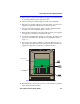
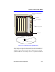
3.10 INTERFACE MODULE SLOT REQUIREMENTS
The slot numbers located on the top front of the chassis are reserved for
specific SmartSwitch 6500 modules. Table 3-1 provides the slot
requirements.
!
CAUTION
The requirements outlined in the following section MUST be
followed for the SmartSwitch 6500 and the installed interface
modules to function properly.
NOTE
Table 3-1 refers to specific interface modules that are required
for the SmartSwitch 6500 to function properly. Refer to your
interface module documentation set to ensure that the required
modules are at the installation site before installing any new
interface modules.
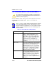
Table 3-1 Interface Module Slot Requirements
Slot Numbers Interface Module(s) allowed in the slot
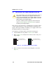
Slots 1 through 6 May contain Translation and Scheduling
Modules (TSMs) that DO NOT have CPUs
installed. These slots may also contain any
other Cabletron Systems SmartSwitch 6000
modules (e.g., 6H252-17, 6H123-50, etc.). If
the 6C110 chassis is using 6C205-2 or
6C205-3 power supplies, only five TSMs may
be installed.
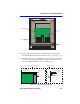
Slots 7 and 8 Reserved for TSMs that have a CPU daughter
board installed. The SmartSwitch 6500 chassis
MUST have at least one TSM with a CPU
daughter board in slot 7 or 8. A second TSM
may be installed to provide redundancy. If the
6C110 chassis is using 6C205-2 or 6C205-3
power supplies, only ONE TSM with a CPU
daughter board may be installed.
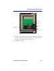
Slots 9 and 10 Reserved for Cell Storage Modules (CSMs).
The SmartSwitch 6500 MUST have at least
one CSM installed in slot 9 or 10. A second
CSM may be added to provide redundancy. If
the 6C110 chassis is using 6C205-2 or
6C205-3 power supplies, only ONE CSM may
be installed.