
Specifications

Chapter 1: Features Overview
12 SSR 8000/8600 Getting Started Guide
Hardware Overview
This section describes the SSR hardware modules with which you will be working.
Chapter 2 in this guide describes how to install the hardware. This section describes the
following hardware:
• Chassis, Backplane, and Fan module
• Control Module
• Power Supply
• Switching Fabric Module (SSR 8600 only)
•Line cards
Chassis
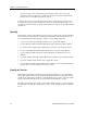
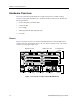
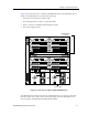
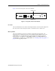
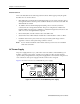
Figure 1 shows the front view of a fully loaded SSR 8000 chassis. The SSR 8000 chassis
contains eight slots, numbered from 0 to 7. Slot 0 is in the lower left corner of the chassis
and slot 7 is in the upper right corner.
Figure 1. Front view of a fully loaded SSR 8000 chassis
6
4
2
7
5
3
CM/1
PS2PS1
CM
21 21
87654321 87654321
87654321 87654321
87
6
5
4
3
21
Fan module Power supply Control module Power supply
Gigabit-LX module
Gigabit-SX module 10/100 BASE-TX
module
100 BASE-FX
module
SSR-CM-2 CONTROL MODULE
10/100BASE-TXSSR-HTX12-08
10/100BASE-TXSSR-HTX12-08
10/100BASE-TXSSR-HTX12-08
10/100BASE-TXSSR-HTX12-08
1000BASE-LXSSR-GLX19-02
SSR-8
1000BASE-SXSSR-GSX11-02
100BASE-FXSSR-HFX11-08
SSR-PS-8
100-125~5A
200-240~3A
50-60 Hz
PWR
SSR-PS-8
100-125~5A
200-240~3A
50-60 Hz
PWR