
Specifications

SSR 8000/8600 Getting Started Guide 15
Chapter 1: Features Overview
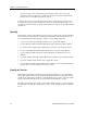
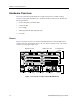
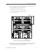
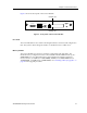
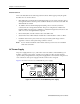
Figure 3 shows the front panel of the Control Module.
Figure 3. Front panel of the Control Module
Boot Flash
The Control Module has a boot flash containing the SSR’s boot software and configuration
files. The system software image file resides on a PCMCIA card or a TFTP server.
Memory Module
The Control Module uses memory to hold the routing tables and other tables. The
minimum factory configuration for the Control Module includes 64MB of memory (in a
64MB DIMM). You can obtain SSR memory upgrade kits from Cabletron Systems to
increase memory to 128MB (in a 128MB DIMM), 192MB (in one 64MB DIMM and one
128MB DIMM), or 256MB (in two 128MB DIMMs). See “Installing a Memory Upgrade” on
page 64 for the upgrade procedure.
10/100 Mgmt
Console
RST
SYS
OK
ERR DIAG
HBT
Hot
Swap
Online Offline
PCMCIA slot 1
SSR-CM-2 CONTROL MODULE
PCMCIA slot 0