
Specifications


Chapter 2: Hardware Installation
78 SSR 8000/8600 Getting Started Guide
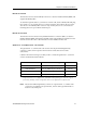
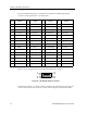
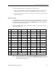
The following table maps the pin assignments for Cabletron’s LFH-60 high density
connectors for the Quad Serial – C/CE line cards.
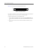
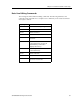
Figure 41 shows the pin positions in the LFH-60 high density connector.
Figure 41. LFH-60 high density connector
Cabletron Quad Serial – C/CE line cards use standard copper twisted-pair cable with one
of four custom remote-end connectors to attach to their respective CSU/DSU modules.
Pin Signal Pin Signal Pin Signal Pin Signal
1 P1_GND 16 P2_TXC_A 31 P1_GND 46 P2_TXD_A
2 P1_MODE[2] 17 P2_TXC_B 32 P1_MODE[0] 47 P2_TXD_B
3 P1_CTS_B 18 P2_DCD_A 33 P1_DCD_B 48 P2_RTS_A
4 P1_CTS_A 19 P2_DCD_B 34 P1_DCD_A 49 P2_RTS_B
5 P1_RTS_B 20P2_MODE[1] 35P0_RXD_B 50P2_DSR_A
6 P1_RTS_A 21 P2_GND 36 P0_RXD_A 51 P2_DSR_B
7 P1_SCTE_B 22 P2_GND 37 Reserved 52 P2_LL_A
8 P1_SCTE_A 23 P1_TXD_A 38 P2_GND 53 P2_SHIELD
9 P1_GND 24 P1_TXD_B 39 P2_MODE[0] 54 Reserved
10 P2_GND 25 P1_TXC_A 40 P2_CTS_B 55 P1_RXC_A
11P2_MODE[2] 26P1_TXC_B 41P2_CTS_A 56P1_RXC_B
12 P2_RXD_B 27 P1_DSR_A 42 P2_DTR_B 57 P1_DTR_A
13 P2_RXD_A 28 P1_DSR_B 43 P2_DTR_A 58 P1_DTR_B
14 P2_RXC_B 29 P1_MODE[1] 44 P2_SCTE_B 59 P1_LL_A
15 P2_RXC_A 30 P1_GND 45 P2_SCTE_A 60 P1_SHIELD
1
30
60
31
46
45
16
15