SmartSwitch Router User Reference Manual 9032578-04
Notice Notice Cabletron Systems reserves the right to make changes in specifications and other information contained in this document without prior notice. The reader should in all cases consult Cabletron Systems to determine whether any such changes have been made. The hardware, firmware, or software described in this manual is subject to change without notice.
Notice Industry Canada Notice This digital apparatus does not exceed the Class A limits for radio noise emissions from digital apparatus set out in the Radio Interference Regulations of the Canadian Department of Communications. Le présent appareil numérique n’émet pas de bruits radioélectriques dépassant les limites applicables aux appareils numériques de la class A prescrites dans le Règlement sur le brouillage radioélectrique édicté par le ministère des Communications du Canada.
Notice CABLETRON SYSTEMS, INC. PROGRAM LICENSE AGREEMENT IMPORTANT: THIS LICENSE APPLIES FOR USE OF PRODUCT IN THE FOLLOWING GEOGRAPHICAL REGIONS: CANADA MEXICO CENTRAL AMERICA SOUTH AMERICA BEFORE OPENING OR UTILIZING THE ENCLOSED PRODUCT, CAREFULLY READ THIS LICENSE AGREEMENT. This document is an agreement (“Agreement”) between You, the end user, and Cabletron Systems, Inc.
Notice Sections 1 or 2 of this Agreement, You agree not to (i) reexport or release the Program, the source code for the Program or technology to a national of a country in Country Groups D:1 or E:2 (Albania, Armenia, Azerbaijan, Belarus, Bulgaria, Cambodia, Cuba, Estonia, Georgia, Iraq, Kazakhstan, Kyrgyzstan, Laos, Latvia, Libya, Lithuania, Moldova, North Korea, the People’s Republic of China, Romania, Russia, Rwanda, Tajikistan, Turkmenistan, Ukraine, Uzbekistan, Vietnam, or such other countries as may b
Notice CABLETRON SYSTEMS SALES AND SERVICE, INC. PROGRAM LICENSE AGREEMENT IMPORTANT: THIS LICENSE APPLIES FOR USE OF PRODUCT IN THE UNITED STATES OF AMERICA AND BY UNITED STATES OF AMERICA GOVERNMENT END USERS. BEFORE OPENING OR UTILIZING THE ENCLOSED PRODUCT, CAREFULLY READ THIS LICENSE AGREEMENT. This document is an agreement (“Agreement”) between You, the end user, and Cabletron Systems Sales and Service, Inc.
Notice Kazakhstan, Kyrgyzstan, Laos, Latvia, Libya, Lithuania, Moldova, North Korea, the People’s Republic of China, Romania, Russia, Rwanda, Tajikistan, Turkmenistan, Ukraine, Uzbekistan, Vietnam, or such other countries as may be designated by the United States Government), (ii) export to Country Groups D:1 or E:2 (as defined herein) the direct product of the Program or the technology, if such foreign produced direct product is subject to national security controls as identified on the U.S.
Notice CABLETRON SYSTEMS LIMITED PROGRAM LICENSE AGREEMENT IMPORTANT: THIS LICENSE APPLIES FOR THE USE OF THE PRODUCT IN THE FOLLOWING GEOGRAPHICAL REGIONS: EUROPE MIDDLE EAST AFRICA ASIA AUSTRALIA PACIFIC RIM BEFORE OPENING OR UTILIZING THE ENCLOSED PRODUCT, CAREFULLY READ THIS LICENSE AGREEMENT.
Notice If the Program is exported from the United States pursuant to the License Exception TSR under the U.S.
Notice SAFETY INFORMATION CLASS 1 LASER TRANSCEIVERS The SSR-HFX11-08 100Base-FX Module, SSR-GSX11-02 1000Base-LX Module, SSR-GLX19-02 1000Base-LX Module, SSR-HFX29-08 100Base-FX SMF Module, SSR-GLX70-01 1000Base-LLX module, SSR-2-SX 1000Base-SX Module, SSR-2-LX 1000Base-LX Module, SSR-2-LX70 1000Base-LX Module, and SSR-2-GSX system use Class 1 Laser transceivers. Read the following safety information before installing or operating these modules.
Notice DECLARATION OF CONFORMITY ADDENDUM Application of Council Directive(s): Manufacturer’s Name: Manufacturer’s Address: European Representative Name: European Representative Address: Conformance to Directive(s)/Product Standards: Equipment Type/Environment: 89/336/EEC 73/23/EEC Cabletron Systems, Inc. 35 Industrial Way PO Box 5005 Rochester, NH 03867 Mr. J.
Notice 12 SmartSwitch Router User Reference Manual
Contents Preface ..................................................................................................... 25 About This Manual ................................................................................................................25 Who Should Read This Manual? .........................................................................................25 How to Use This Manual ......................................................................................................
Contents Chapter 2: Hot Swapping Line Cards and Control Modules ................ 49 Hot Swapping Overview...................................................................................................... 49 Hot Swapping Line Cards.................................................................................................... 49 Deactivating the Line Card........................................................................................... 50 Removing the Line Card .............................
Contents Creating a non-IP/non-IPX VLAN ..............................................................................67 Chapter 4: SmartTRUNK Configuration Guide...................................... 69 Overview .................................................................................................................................69 Configuring SmartTRUNKs .................................................................................................70 Creating a SmartTRUNK ...................
Contents Monitoring IP Parameters............................................................................................. 92 Configuring Router Discovery ............................................................................................ 92 Configuration Examples....................................................................................................... 93 Assigning IP/IPX Interfaces .........................................................................................
Contents Configuring OSPF over Non-Broadcast Multiple Access .......................................120 Monitoring OSPF..................................................................................................................121 OSPF Configuration Examples...........................................................................................122 Exporting All Interface & Static Routes to OSPF .......................................123 Exporting All RIP, Interface & Static Routes to OSPF.........
Contents Authentication .............................................................................................................. 170 Authentication Methods ...................................................................................... 170 Authentication Keys and Key Management ..................................................... 171 Configuring Simple Routing Policies ............................................................................... 171 Redistributing Static Routes ............
Contents IGMP Overview ............................................................................................................199 DVMRP Overview ........................................................................................................200 Configuring IGMP ...............................................................................................................201 Configuring IGMP on an IP Interface ........................................................................
Contents Using Dynamic NAT ............................................................................................ 228 Dynamic NAT with IP Overload (PAT) Configuration ......................................... 229 Using Dynamic NAT with IP Overload ............................................................ 230 Dynamic NAT with Outside Interface Redundancy .............................................. 230 Using Dynamic NAT with Matching Interface Redundancy .........................
Contents Enabling IPX RIP...........................................................................................................249 Enabling SAP .................................................................................................................249 Configuring Static Routes............................................................................................249 Configuring Static SAP Table Entries ........................................................................
Contents Configuring Layer-2 Static Entry Filters................................................................... 277 Configuring Layer-2 Secure Port Filters ................................................................... 277 Monitoring Layer-2 Security Filters .......................................................................... 278 Layer-2 Filter Examples............................................................................................... 279 Example 1: Address Filters .............
Contents Control Tables ...............................................................................................................303 Using RMON ........................................................................................................................304 Configuring RMON Groups...............................................................................................305 Configuration Examples ............................................................................................
Contents Compression on MLP Bundles or Links............................................................ 329 Monitoring PPP WAN Ports.............................................................................................. 330 PPP Port Configuration ...................................................................................................... 330 WAN Configuration Examples ......................................................................................... 332 Simple Configuration File ..
Preface About This Manual This manual provides detailed information and procedures for configuring the SmartSwitch Router (SSR) software. If you have not yet installed the SSR, use the instructions in the SmartSwitch Router Getting Started Guide to install the chassis and perform basic setup tasks, then return to this manual for more detailed configuration information. Who Should Read This Manual? Read this manual if you are a network administrator responsible for configuring and monitoring the SSR.
Preface If You Want To 26 See Configure VRRP Chapter 7, “VRRP Configuration Guide” on page 95 Configure RIP routing Chapter 8, “RIP Configuration Guide” on page 109 Configure OSPF routing Chapter 9, “OSPF Configuration Guide” on page 115 Configure BGP routing Chapter 10, “BGP Configuration Guide” on page 127 Configure routing policies Chapter 11, “Routing Policy Configuration Guide” on page 163 Configure IP multicast routing Chapter 12, “Multicast Routing Configuration Guide” on page 199 Con
Preface Related Documentation The SmartSwitch Router documentation set includes the following items. Refer to these other documents to learn more about your product.
Preface 28 SmartSwitch Router User Reference Manual
Chapter 1 SSR Product Overview The SmartSwitch Router (SSR) provides non-blocking, wire-speed Layer-2 (switching), Layer-3 (routing) and Layer-4 (application) switching. The hardware provides wire-speed performance regardless of the performance monitoring, filtering, and Quality of Service (QoS) features enabled by the software. You do not need to accept performance compromises to run QoS or access control lists (ACLs).
Chapter 1: SSR Product Overview Table 1.
Chapter 1: SSR Product Overview Table 1. SSR Hardware and software specifications (Continued) Feature Quality of Service (QoS) Specification • Layer-2 prioritization (802.
Chapter 1: SSR Product Overview – Routing Information Protocol (RIP) Version 1, 2 Chapter 6, “IP Routing Configuration Guide” on page 85 describes these protocols in detail. • Exterior gateway protocol: – Border Gateway Protocol (BGP) Version 2,3,4 Chapter 10, “BGP Configuration Guide” on page 127 describes this protocol in detail.
Chapter 1: SSR Product Overview Basic Line Editing Commands The CLI supports EMACs-like line editing commands. The following table lists some commonly used commands. Table 2.
Chapter 1: SSR Product Overview Note: The command prompt will show the name of the SmartSwitch Router in front of the mode character(s). The default name is “ssr”. When you are in Configure or Enable mode, enter the exit command or press Ctrl+Z to exit to the previous access mode. Note: When you exit Configure mode, the CLI will ask you whether you want to activate the configuration commands you have issued.
Chapter 1: SSR Product Overview multicast ping pvst sfs statistics stp telnet traceroute vlan - - Configure Multicast related parameters - Ping utility - Show Per Vlan Spanning Tree Protocol (PVST) parameters - Show SecureFast Switching (SFS) parameters - Show or clear SSR statistics Show STP status Telnet utility Traceroute utility Show VLAN-related parameters Enable Mode Enable mode provides more facilities than User mode.
Chapter 1: SSR Product Overview ip ip-policy ip-redundancy ip-router ipx l2-tables lfap load-balance logout mtrace multicast nat ntp ospf ping port ppp pvst qos radius rate-limit rdisc reboot rip rmon sfs smarttrunk snmp statistics stp system tacacs tacacs-plus telnet traceroute vlan web-cache - Show IP related parameters Show IP policy information Show IP Redundancy information (VRRP) Show unicast IP Routing related parameters Show IPX related parameters Show L2 Tables information - Show LFAP parameters
Chapter 1: SSR Product Overview Configure Mode Configure mode provides the capabilities to configure all features and functions on the SSR. You can configure features and functions within Configure mode including router configuration, access control lists and spanning tree. To list the Configure commands, enter: List the Configure commands.
Chapter 1: SSR Product Overview pvst qos radius rate-limit rdisc rip rmon sfs smarttrunk snmp stp system tacacs tacacs-plus vlan web-cache - Configure (PVST) - Configure - Configure - Configure - Configure - Configure - Configure - Configure - Configure - Configure - Configure - Configure - Configure - Configure - Configure - Configure Per Vlan Spanning Tree Protocol Quality of Service parameters RADIUS related parameters rate limits for flows Router Discovery Protocol Routing Information Protocol (RIP)
Chapter 1: SSR Product Overview Disabling a Function or Feature The CLI provides for an implicit negate. This allows for the “disabling” of a feature or function which has been “enabled”. Use the negate command on a specific line of the active configuration to “disable” a feature or function which has been enabled. For example, Spanning Tree Protocol is disabled by default.
Chapter 1: SSR Product Overview Loading System Image Software By default, the SSR boots using the system image software installed on the Control Module’s PCMCIA flash card. To upgrade the system software and boot using the upgraded image, use the following procedure. 1. Display the current boot settings by entering the system show version command: Here is an example: ssr# system show version Software Information Software Version : 2.1 Copyright : Copyright (c) 1996-1998 Cabletron Systems, Inc.
Chapter 1: SSR Product Overview 6. Enter the system image list command to verify the change. Note: You do not need to activate this change. Loading Boot PROM Software The SSR boots using the boot PROM software installed on the Control Module’s internal memory. To upgrade the boot PROM software and boot using the upgraded image, use the following procedure. 1.
Chapter 1: SSR Product Overview 1. If you have not already done so, enter the enable command to enter Enable mode in the CLI. 2. If you have not already done so, enter the configure command to enter Configure mode in the CLI. 3. Enter the following command: save active 4. The CLI displays the following message: Do you want to make the changes Active? [y] 5. Enter yes or y to activate the changes.
Chapter 1: SSR Product Overview Displaying Configuration Changes While in Configure mode, you can display the configuration of the running system as well as non-activated changes that are in the Scratchpad by entering the following command: Display running system configuration and non-activated changes in scratchpad. show While in Enable mode, you can display the active configuration of the system by entering the following command: Display active configuration of the system.
Chapter 1: SSR Product Overview • Configuring DNS • Connecting between the SSR and other systems Setting the SSR Name The SSR name is set to ssr by default. You may customize the name for the SSR by entering the following command in Configure mode: Set the SSR name. system set name Setting SSR Date and Time The SSR system time can keep track of time as entered by the user or via NTP.
Chapter 1: SSR Product Overview Configuring the SSR CLI You can customize the CLI display format to a desired line length or row count. To configure the CLI terminal display, enter the following command in Enable mode: Configure the CLI terminal display. cli set terminal rows columns Configuring SNMP Services The SSR accepts SNMP sets and gets from an SNMP manager. You can configure SSR SNMP parameters including community strings and trap server target addresses.
Chapter 1: SSR Product Overview Connecting Between the SSR and Other Systems To test a connection between the SSR and an IP host, enter the following command in User or Enable mode: Test connection between the SSR and an IP host. ping packets size wait [flood] [dontroute] To open a Telnet session from the SSR to an IP host, enter the following command in User or Enable mode: Telnet to a specified IP host.
Chapter 1: SSR Product Overview Monitoring Configuration The SSR provides many commands for displaying configuration information. After you add configuration items and commit them to the active configuration, you can display them using the following commands. Task Command Display history buffer. cli show history Show terminal settings. cli show terminal Show all accesses to the SNMP agent. snmp show access Show all SNMP information. snmp show all Show chassis ID.
Chapter 1: SSR Product Overview Task 48 Command Show SSR location. system show location Show the SSR login banner. system show login-banner Show SSR name. system show name Show the type of Power-On Self Test (POST) that should be performed. system show poweron-selftestmode Show the configuration changes in the scratchpad. These changes have not yet been activated. system show scratchpad Show the startup configuration for the next reboot.
Chapter 2 Hot Swapping Line Cards and Control Modules Hot Swapping Overview This chapter describes the hot swapping functionality of the SSR. Hot swapping is the ability to replace a line card or Control Module while the SSR is operating. Hot swapping allows you to remove or install line cards without switching off or rebooting the SSR. Swapped-in line cards are recognized by the SSR and begin functioning immediately after they are installed.
Chapter 2: Hot Swapping Line Cards and Control Modules Deactivating the Line Card To deactivate the line card, do one of the following: • Press the Hot Swap button on the line card. The Hot Swap button is recessed in the line card's front panel. Use a pen or similar object to reach it. When you press the Hot Swap button, the Offline LED lights. Figure 1 shows the location of the Offline LED and Hot Swap button on a 1000Base-SX line card.
Chapter 2: Hot Swapping Line Cards and Control Modules Warning: Do not remove the line card unless the Offline LED is lit. Doing so can cause the SSR to crash. 2. Loosen the captive screws on each side of the line card. 3. Carefully remove the line card from its slot in the SSR chassis. Installing a New Line Card To install a new line card: 1.
Chapter 2: Hot Swapping Line Cards and Control Modules Warning: You can only hot swap an inactive Control Module. You should never remove the active Control Module from the SSR. Doing so will crash the system. The procedure for hot swapping a control module is similar to the procedure for hot swapping a line card. You must deactivate the Control Module, remove it from the SSR, and insert another Control Module or line card in the slot. Deactivating the Control Module To deactivate the Control Module: 1.
Chapter 2: Hot Swapping Line Cards and Control Modules Installing the Control Module To install a new Control Module or line card into the slot: Note: 1. You can install either a line card or a Control Module in slot CM/1, but you can install only a Control Module in slot CM. Slide the Control Module or line card all the way into the slot, firmly but gently pressing it fully in place to ensure that the pins on the back of the card are completely seated in the backplane. Note: 2.
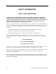
Chapter 2: Hot Swapping Line Cards and Control Modules The Online LED goes out and the Offline LED lights. Figure 3 shows the location of the Offline LED and Hot Swap button on a Switching Fabric Module. Offline LED SSR-SF-16 Switching Fabric Offline Online Hot Active Swap Hot Swap Button Figure 3. Location of Offline LED and Hot Swap button on a Switching Fabric Module To remove the Switching Fabric Module: 1. Loosen the captive screws on each side of the Switching Fabric Module. 2.
Chapter 3 Bridging Configuration Guide Bridging Overview The SmartSwitch Router provides the following bridging functions: • Compliance with the IEEE 802.
Chapter 3: Bridging Configuration Guide Bridging Modes (Flow-Based and Address-Based) The SSR provides the following types of wire-speed bridging: Address-based bridging - The SSR performs this type of bridging by looking up the destination address in an L2 lookup table on the line card that receives the bridge packet from the network. The L2 lookup table indicates the exit port(s) for the bridged packet. If the packet is addressed to the SSR's own MAC address, the packet is routed rather than bridged.
Chapter 3: Bridging Configuration Guide • Multicast based • Policy based Detailed information about these types of VLANs is beyond the scope of this manual. Each type of VLAN is briefly explained in the following subsections. Port-based VLANs Ports of L2 devices (switches, bridges) are assigned to VLANs. Any traffic received by a port is classified as belonging to the VLAN to which the port belongs.
Chapter 3: Bridging Configuration Guide Multicast-based VLANs Multicast-based VLANs are created dynamically for multicast groups. Typically, each multicast group corresponds to a different VLAN. This ensures that multicast frames are received only by those ports that are connected to members of the appropriate multicast group. Policy-based VLANs Policy-based VLANs are the most general definition of VLANs.
Chapter 3: Bridging Configuration Guide the SSR as a result of creating L3 interfaces for IP and/or IPX. However, these implicit VLANs do not need to be created or configured manually. The implicit VLANs created by the SSR are subnet-based VLANs. Most commonly, an SSR is used as a combined switch and router. For example, it may be connected to two subnets S1 and S2. Ports 1-8 belong to S1 and ports 9-16 belong to S2.
Chapter 3: Bridging Configuration Guide For example, if port 1 belongs to VLAN IPX_VLAN for IPX, VLAN IP_VLAN for IP and VLAN OTHER_VLAN for any other protocol, then an IP frame received by port 1 is classified as belonging to VLAN IP_VLAN. Trunk ports (802.1Q) are usually used to connect one VLAN-aware switch to another. They carry traffic belonging to several VLANs. For example, suppose that SSR A and B are both configured with VLANs V1 and V2.
Chapter 3: Bridging Configuration Guide SSR A B C The corresponding bridge tables for address-based and flow-based bridging are shown below. As shown, the bridge table contains more information on the traffic patterns when flow-based bridging is enabled compared to address-based bridging.
Chapter 3: Bridging Configuration Guide The SSR supports per VLAN spanning tree. By default, all the VLANs defined belong to the default spanning tree. You can create a separate instance of spanning tree using the following command: Create spanning tree for a VLAN. pvst create spanningtree vlan-name By default, spanning tree is disabled on the SSR. To enable spanning tree on the SSR, you perform the following tasks on the ports where you want spanning tree enabled..
Chapter 3: Bridging Configuration Guide To set the bridge priority, enter the following command in Configure mode: Set the bridge priority for default spanning tree. stp set bridging priority Set the bridge priority for a particular instance of spanning tree. pvst set bridging spanning-tree priority Setting a Port Priority You can set a priority for an interface. When two bridges tie for position as the root bridge, you configure an interface priority to break the tie.
Chapter 3: Bridging Configuration Guide • Define the Maximum Idle Interval Adjusting the Interval between Hello Times You can specify the interval between hello time. To adjust this interval, enter the following command in Configure mode: Specify the interval between hello time for default spanning tree. stp set bridging hello-time Specify the interval between hello time for a particular instance of spanning tree.
Chapter 3: Bridging Configuration Guide Configuring a Port or Protocol based VLAN To create a port or protocol based VLAN, perform the following steps in the Configure mode. 1. Create a port or protocol based VLAN. 2. Add physical ports to a VLAN. Creating a Port or Protocol Based VLAN To create a VLAN, enter the following command in Configure mode. Create a VLAN. vlan create id Adding Ports to a VLAN To add ports to a VLAN, enter the following command in Configure mode.
Chapter 3: Bridging Configuration Guide Configuring Layer-2 Filters Layer-2 security filters on the SSR allow you to configure ports to filter specific MAC addresses. When defining a Layer-2 security filter, you specify to which ports you want the filter to apply. Refer to the “Security Configuration Chapter” for details on configuring Layer-2 filters.
Chapter 3: Bridging Configuration Guide Show information on MACs registered. l2-table show bridge-management Show all VLANs. vlan show Configuration Examples VLANs are used to associate physical ports on the SSR with connected hosts that may be physically separated but need to participate in the same broadcast domain. To associate ports to a VLAN, you must first create a VLAN and then assign ports to the VLAN.
Chapter 3: Bridging Configuration Guide 68 SmartSwitch Router User Reference Manual
Chapter 4 SmartTRUNK Configuration Guide Overview This chapter explains how to configure and monitor SmartTRUNKs on the SSR. A SmartTRUNK is Cabletron Systems’ technology for load balancing and load sharing. For a description of the SmartTRUNK commands, see the “smarttrunk commands” section of the SSR Command Line Interface Manual. On the SSR, a SmartTRUNK is a group of two or more ports that have been logically combined into a single port.
Chapter 4: SmartTRUNK Configuration Guide Configuring SmartTRUNKs To create a SmartTRUNK: 1. Create a SmartTRUNK and specify a control protocol for it. 2. Add physical ports to the SmartTRUNK. 3. Specify the policy for distributing traffic across SmartTRUNK ports. This step is optional; by default, the SSR distributes traffic to ports in a round-robin (sequential) manner.
Chapter 4: SmartTRUNK Configuration Guide To add ports to a SmartTRUNK, enter the following command in Configure mode:: Create a SmartTRUNK that will be connected to a device that supports the DEC Hunt Group control protocol. smarttrunk add ports to Specify Traffic Distribution Policy (Optional) The default policy for distributing traffic across the ports in a SmartTRUNK is “roundrobin,” where the SSR selects the port on a rotating basis.
Chapter 4: SmartTRUNK Configuration Guide Example Configurations The following shows a network design based on SmartTRUNKs. R1 is an SSR operating as a router, while S1 and S2 are SSRs operating as switches. Cisco 7500 Router st.1 10.1.1.1/24 st.2 10.1.1.2/24 to-cisco Router R1 11.1.1.2/24 to-s1 st.4 Switch S1 Server 12.1.1.2/24 to-s2 st.3 Switch S2 st.5 Cisco Catalyst 5K Switch The following is the configuration for the Cisco 7500 router: interface port-channel 1 ip address 10.1.1.1 255.255.
Chapter 4: SmartTRUNK Configuration Guide The following is the SmartTRUNK configuration for the SSR labeled ‘R1’ in the diagram: smarttrunk create st.1 protocol no-protocol smarttrunk create st.2 protocol huntgroup smarttrunk create st.3 protocol huntgroup smarttrunk add ports et.1(1-2) to st.1 smarttrunk add ports et.2(1-2) to st.2 smarttrunk add ports et.3(1-2) to st.3 interface create ip to-cisco address-netmask 10.1.1.2/24 port st.1 interface create ip to-s1 address-netmask 11.1.1.2/24 port st.
Chapter 4: SmartTRUNK Configuration Guide 74 SmartSwitch Router User Reference Manual
Chapter 5 DHCP Configuration Guide DHCP Overview The Dynamic Host Configuration Protocol (DHCP) server on the SSR provides dynamic address assignment and configuration to DHCP capable end-user systems, such as Windows 95/98/NT and Apple Macintosh systems. You can configure the server to provide a dynamic IP address from a pre-allocated pool of IP addresses or a static IP address.
Chapter 5: DHCP Configuration Guide Configuring DHCP By default, the DHCP server is not enabled on the SSR. You can selectively enable DHCP service on particular interfaces and not others. To enable DHCP service on an interface, you must first define a DHCP scope. A scope consists of a pool of IP addresses and a set of parameters for a DHCP client. The parameters are used by the client to configure its network environment, for example, the default gateway and DNS domain name.
Chapter 5: DHCP Configuration Guide Table 3. Client Parameters Parameter Value netbios-name-server IP address of NetBIOS Name Server (WINS server) netbios-node-type NetBIOS node type of the client netbios-scope NetBIOS scope of the client To define the parameters that the DHCP server gives the clients, enter the following command in Configure mode: Define client parameters. dhcp define parameters ...
Chapter 5: DHCP Configuration Guide Configuring DHCP Server Parameters You can configure several “global” parameters that affect the behavior of the DHCP server itself. To configure global DHCP server parameters, enter the following commands in Configure mode: Specify a remote location to back up the lease database. dhcp global set lease-database Specify the intervals at which the lease database is updated.
Chapter 5: DHCP Configuration Guide DHCP Configuration Examples The following configuration describes DHCP configuration for a simple network with just one interface on which DHCP service is enabled to provide both dynamic and static IP addresses. 1. Create an IP VLAN called ‘client_vlan’. vlan create client_vlan ip 2. Add all Fast Ethernet ports in the SSR to the VLAN ‘client_vlan’. vlan add port et.*.* to client_vlan 3. Create an IP interface called ‘clients’ with the address 10.1.1.
Chapter 5: DHCP Configuration Guide 9. Specify a remote lease database on the TFTP server 10.1.89.88. dhcp global set lease-database tftp://10.1.89.88/lease.db 10. Specify a database update interval of every 15 minutes. dhcp global set commit-interval 15 Configuring Secondary Subnets In some network environments, multiple logical subnets can be imposed on a single physical segment. These logical subnets are sometimes referred to as “secondary subnets” or “secondary networks.
Chapter 5: DHCP Configuration Guide 6. Include ‘scope2’ in the superscope ‘super1’. dhcp scope2 attach superscope super1 Since there are multiple pools of IP addresses, the pool associated with ‘scope1’ is used first since ‘scope1’ is applied to the interface before ‘scope2’. Clients that are given an address from ‘scope1’ will also be given parameters from ‘scope1,’ which includes the default gateway 10.1.1.1 that resides on the 10.1.x.x subnet.
Chapter 5: DHCP Configuration Guide 6. Define the address pool for ‘scope2’. dhcp scope2 define pool 10.2.1.40-10.2.1.50 7. Create a superscope ‘super1’ that includes ‘scope1’. dhcp scope1 attach superscope super1 8. Include ‘scope2’ in the superscope ‘super1’. dhcp scope2 attach superscope super1 For clients on the secondary subnet, the default gateway is 10.2.1.1, which is also the secondary address for the interface ‘clients’.
Chapter 5: DHCP Configuration Guide 4. Define the address pool for ‘scope1’. dhcp scope1 define pool 10.5.1.10-10.5.1.
Chapter 5: DHCP Configuration Guide 84 SmartSwitch Router User Reference Manual
Chapter 6 IP Routing Configuration Guide This chapter describes how to configure IP interfaces and general non-protocol-specific routing parameters. IP Routing Overview Internet Protocol (IP) is a packet-based protocol used to exchange data over computer networks. IP handles addressing, routing, fragmentation, reassembly, and protocol demultiplexing. In addition, IP specifies how hosts and routers should process packets, handle errors and discard packets.
Chapter 6: IP Routing Configuration Guide The SSR supports standards-based TCP, UDP, and IP. IP Routing Protocols The SSR supports standards-based unicast and multicast routing. Unicast routing protocol support includes Interior Gateway Protocols and Exterior Gateway Protocols. Multicast routing protocols are used to determine how multicast data is transferred in a routed environment.
Chapter 6: IP Routing Configuration Guide Configuring IP Interfaces and Parameters This section provides an overview of configuring various IP parameters and setting up IP interfaces. Configuring IP Addresses to Ports You can configure one IP interface directly to physical ports. Each port can be assigned multiple IP addresses representing multiple subnets connected to the physical port. To configure an IP interface to a port, enter one of the following commands in Configure mode.
Chapter 6: IP Routing Configuration Guide • 802.3 SNAP: SNAP IEEE 802.3 encapsulation, in which the type code becomes the frame length for the IEEE 802.2 LLC encapsulation (destination and source Service Access Points, and a control byte) To configure IP encapsulation, enter one of the following commands in Configure mode. Configure Ethernet II encapsulation. interface create ip output-macencapsulation ethernet_II Configure 802.3 SNAP encapsulation.
Chapter 6: IP Routing Configuration Guide Configuring Reverse Address Resolution Protocol (RARP) Reverse Address Resolution Protocol (RARP) works exactly the opposite of ARP. Taking a MAC address as input, RARP determines the associated IP address. RARP is useful for Xterminals and diskless workstations that may not have an IP address when they boot. They can submit their MAC address to a RARP server on the SSR, which returns an IP address.
Chapter 6: IP Routing Configuration Guide Monitoring RARP You can use the following commands to obtain information about the SSR’s RARP configuration: Display the interfaces to which the RARP server responds. rarpd show interface Display the existing MAC-to-IP address mappings rarpd show mappings Display RARP statistics. statistics show rarp |all Configuring DNS Parameters The SSR can be configured to specify DNS servers, which supply name services for DNS requests.
Chapter 6: IP Routing Configuration Guide Configuring IP Helper You can configure the SSR to forward UDP broadcast packets received on a given interface to all other interfaces or to a specified IP address. You can specify a UDP port number for which UDP broadcast packets with that destination port number will be forwarded.
Chapter 6: IP Routing Configuration Guide packets to be processed on the SSR even if directed broadcast is not enabled on the interface receiving the packet. Similarly, the SSR installs flows to drop packets destined for the SSR for which service is not provided by the SSR. This prevents packets for unknown services from slowing the CPU. You can disable this behavior, causing these packets to be processed by the CPU.: Disables the directedbroadcast-protection feature of the SSR.
Chapter 6: IP Routing Configuration Guide address or an interface is configured for the limited broadcast address 255.255.255.255, the router advertisement includes all IP addresses configured on the physical interface. When router advertisements are sent to a net or subnet broadcast, then only the address associated with the net or subnet is included. To start and stop router discovery on the SSR, enter the following commands in Configure mode: Start router discovery. rdisc start Stop router discovery.
Chapter 6: IP Routing Configuration Guide You can also assign an IP or IPX interface directly to a physical port. For example, to assign an IP interface ‘RED’ to physical port et.3.4, perform the following: ssr(config)# interface create ip RED address-netmask 10.50.0.0/255.255.0.0 port et.3.
Chapter 7 VRRP Configuration Guide VRRP Overview This chapter explains how to set up and monitor the Virtual Router Redundancy Protocol (VRRP) on the SSR. VRRP is defined in RFC 2338. End host systems on a LAN are often configured to send packets to a statically configured default router. If this default router becomes unavailable, all the hosts that use it as their first hop router become isolated on the network. VRRP provides a way to ensure the availabilty of an end host’s default router.
Chapter 7: VRRP Configuration Guide Basic VRRP Configuration Figure 4 shows a basic VRRP configuration with a single virtual router. Routers R1 and R2 are both configured with one virtual router (VRID=1). Router R1 serves as the Master and Router R2 serves as the Backup. The four end hosts are configured to use 10.0.0.1/16 as the default route. IP address 10.0.0.1/16 is associated with virtual router VRID=1. Master Backup R1 R2 VRID=1 Interface Addr. = 10.0.0.1/16 VRID=1; Addr. = 10.0.0.
Chapter 7: VRRP Configuration Guide In VRRP, the router that owns the IP address associated with the virtual router is the Master. Any other routers that participate in this virtual router are Backups. In this configuration, Router R1 is the Master for virtual router VRID=1 because it owns 10.0.0.1/16, the IP address associated with virtual router VRID=1. Configuration for Router R2 The following is the configuration file for Router R2 in Figure 4. 1: 2: 3: 4: interface create ip test address-netmask 10.
Chapter 7: VRRP Configuration Guide Master for VRID=1 Backup for VRID=2 Master for VRID=2 Backup for VRID=1 R1 R2 Interface Addr. = 10.0.0.1/16 VRID=1; Addr. = 10.0.0.1/16 VRID=2; Addr. = 10.0.0.2/16 H1 VRID=1 10.0.0.1/16 H2 Default Route = 10.0.0.1/16 VRID=2 10.0.0.2/16 Interface Addr. = 10.0.0.2/16 VRID=1; Addr. = 10.0.0.1/16 VRID=2; Addr. = 10.0.0.2/16 H3 H4 Default Route = 10.0.0.2/16 Figure 5. Symmetrical VRRP Configuration In this configuration, half the hosts use 10.0.0.
Chapter 7: VRRP Configuration Guide On line 5, Router R1 associates IP address 10.0.0.2/16 with virtual router VRID=2. However, since Router R1 does not own IP address 10.0.0.2/16, it is not the default Master for virtual router VRID=2. Configuration of Router R2 The following is the configuration file for Router R2 in Figure 5. 1: interface create ip test address-netmask 10.0.0.2/16 port et.1.
Chapter 7: VRRP Configuration Guide Master for VRID=1 1st Backup for VRID=2 1st Backup for VRID=3 Master for VRID=2 1st Backup for VRID=1 2nd Backup for VRID=3 Master for VRID=3 2nd Backup for VRID=1 2nd Backup for VRID=2 R1 R2 R3 VRID=1 10.0.0.1/16 H1 H2 Default Route = 10.0.0.1/16 VRID=3 VRID=2 10.0.0.3/16 10.0.0.2/16 H3 H4 Default Route = 10.0.0.2/16 H5 H6 Default Route = 10.0.0.3/16 Figure 6.
Chapter 7: VRRP Configuration Guide Configuration of Router R1 The following is the configuration file for Router R1 in Figure 6. 1: interface create ip test address-netmask 10.0.0.1/16 port et.1.1 ! 2: ip-redundancy create vrrp 1 interface test 3: ip-redundancy create vrrp 2 interface test 4: ip-redundancy create vrrp 3 interface test ! 5: ip-redundancy associate vrrp 1 interface test address 10.0.0.1/16 6: ip-redundancy associate vrrp 2 interface test address 10.0.0.
Chapter 7: VRRP Configuration Guide The following table shows the priorities for each virtual router configured on Router R1. Virtual Router Default Priority Configured Priority VRID=1 – IP address=10.0.0.1/16 255 (address owner) 255 (address owner) VRID=2 – IP address=10.0.0.2/16 100 200 (see line 8) VRID=3 – IP address=10.0.0.3/16 100 200 (see line 9) Configuration of Router R2 The following is the configuration file for Router R2 in Figure 6. 1: interface create ip test address-netmask 10.
Chapter 7: VRRP Configuration Guide Note: Since 100 is the default priority, line 9, which sets the priority to 100, is actually unnecessary. It is included for illustration purposes only. Configuration of Router R3 The following is the configuration file for Router R3 in Figure 6. 1: interface create ip test address-netmask 10.0.0.3/16 port et.1.
Chapter 7: VRRP Configuration Guide Setting the Backup Priority As described in “Multi-Backup Configuration” on page 99, you can specify which Backup router takes over when the Master router goes down by setting the priority for the Backup routers. To set the priority for a Backup router, enter the following command in Configure mode: Set the Backup priority for a virtual router. ip-redundancy set vrrp interface priority The priority can be between 1 (lowest) and 254.
Chapter 7: VRRP Configuration Guide Setting an Authentication Key By default, no authentication of VRRP packets is performed on the SSR. You can specify a clear-text password to be used to authenticate VRRP exchanges. To enable authentication, enter the following command in Configure mode: Set an authentication key for a virtual router. ip-redundancy set vrrp interface auth-type text auth-key where is a clear-text password.
Chapter 7: VRRP Configuration Guide ip-redundancy show The ip-redundancy show command reports information about a VRRP configuration. To display VRRP information, enter the following commands in Enable mode. Display information about all virtual routers. ip-redundancy show vrrp Display information about all virtual routers on a specified interface.
Chapter 7: VRRP Configuration Guide • A virtual router will respond to ARP requests with a virtual MAC address. This virtual MAC depends on the virtual router ID: virtual MAC address = 00005E:0001XX where XX is the virtual router ID This virtual MAC address is also used as the source MAC address of the keep-alive Advertisements transmitted by the Master router. • If multiple virtual routers are created on a single interface, the virtual routers must have unique identifiers.
Chapter 7: VRRP Configuration Guide 108 SmartSwitch Router User Reference Manual
Chapter 8 RIP Configuration Guide RIP Overview This chapter describes how to configure the Routing Information Protocol (RIP) on the SmartSwitch Router. RIP is a distance-vector routing protocol for use in small networks. RIP is described in RFC 1723. A router running RIP broadcasts updates at set intervals. Each update contains paired values where each pair consists of an IP network address and an integer distance to that network. RIP uses a hop count metric to measure the distance to a destination.
Chapter 8: RIP Configuration Guide Enabling and Disabling RIP To enable or disable RIP, enter one of the following commands in Configure mode. Enable RIP. rip start Disable RIP. rip stop Configuring RIP Interfaces To configure RIP in the SSR, you must first add interfaces to inform RIP about attached interfaces. To add RIP interfaces, enter the following commands in Configure mode. Add interfaces to the RIP process.
Chapter 8: RIP Configuration Guide RIP Parameter Default Value Authentication None Update interval 30 seconds To change RIP parameters, enter the following commands in Configure mode. Set RIP Version on an interface to RIP V1. rip set interface |all version 1 Set RIP Version on an interface to RIP V2. rip set interface |all version 2 Specify that RIP V2 packets should be multicast on this interface.
Chapter 8: RIP Configuration Guide Enable acceptance of RIP routes that have a metric of zero. rip set check-zero-metric disable|enable Enable poison revers, as specified by RFC 1058. rip set poison-reverse disable|enable Configuring RIP Route Preference You can set the preference of routes learned from RIP. To configure RIP route preference, enter the following command in Configure mode. Set the preference of routes learned from RIP.
Chapter 8: RIP Configuration Guide Show RIP information on the specified interface. rip show interface Show RIP interface policy information. rip show interface-policy Show detailed information of all RIP packets. rip trace packets detail Show detailed information of all packets received by the router. rip trace packets receive Show detailed information of all packets sent by the router. rip trace packets send Show detailed information of all request received by the router.
Chapter 8: RIP Configuration Guide ! ! Change default metric-out rip set interface SSR1-if1 metric-out 3 114 SmartSwitch Router User Reference Manual
Chapter 9 OSPF Configuration Guide OSPF Overview Open Shortest Path First (OSPF) is a link-state routing protocol that supports IP subnetting and authentication. The SSR supports OSPF Version 2.0 as defined in RFC 1583. Each link-state message contains all the links connected to the router with a specified cost associated with the link. The SSR supports the following OSPF functions: • Stub Areas: Definition of stub areas is supported.
Chapter 9: OSPF Configuration Guide OSPF Multipath The SSR also supports OSPF and static Multi-path. If multiple equal-cost OSPF or static routes have been defined for any destination, then the SSR “discovers” and uses all of them. The SSR will automatically learn up to four equal-cost OSPF or static routes and retain them in its forwarding information base (FIB). The forwarding module then installs flows for these destinations in a round-robin fashion.
Chapter 9: OSPF Configuration Guide Configuring OSPF Interface Parameters You can configure the OSPF interface parameters shown in the table below. Table 4. OSPF Interface Parameters OSPF Parameter Default Value Interface OSPF State (Enable/Disable) Enable (except for virtual links) Cost 1 No multicast Default is using multicast mechanism.
Chapter 9: OSPF Configuration Guide Specify the number of seconds required to transmit a link state update on an OSPF interface. ospf set interface |all transit-delay Specify the time a neighbor router will listen for OSPF hello packets before declaring the router down. ospf set interface |all router-dead-interval Disable IP multicast for sending OSPF packets to neighbors on an OSPF interface.
Chapter 9: OSPF Configuration Guide Add a stub host to an OSPF area. ospf add stub-host [to-area |backbone] [cost ] Add a network to an OSPF area for summarization. ospf add network [to-area |backbone] [restrict] [host-net] Configuring OSPF Area Parameters The SSR allows configuration of various OSPF area parameters, including stub areas, stub cost and authentication method. Stub areas are areas into which information on external routes is not sent.
Chapter 9: OSPF Configuration Guide To configure virtual links, enter the following commands in the Configure mode. Create a virtual link. ospf add virtual-link [neighbor ] [transit-area ] Set virtual link parameters.
Chapter 9: OSPF Configuration Guide Monitoring OSPF The SSR lets you display OSPF statistics and configurations contained in the routing table. Information displayed provides routing and performance information. To display OSPF information, enter the following commands in Enable mode. Show IP routing table. ip show table routing Monitor OSPF error conditions. ospf monitor errors destination Show information on all interfaces configured for OSPF.
Chapter 9: OSPF Configuration Guide Show OSPF interfaces. ospf show interfaces Shows information about all valid next hops mostly derived from the SPF calculation. ospf show next-hop-list Show OSPF statistics. ospf show statistics Shows information about OSPF Border Routes. ospf show summary-asb Show OSPF timers. ospf show timers Show OSPF virtual-links.
Chapter 9: OSPF Configuration Guide ospf add interface 140.1.2.1 to-area 140.1.0.0 ospf add interface 140.1.3.1 to-area 140.1.0.0 ospf add interface 130.1.1.1 to-area backbone Exporting All Interface & Static Routes to OSPF Router R1 has several static routes. We would export these static routes as type-2 OSPF routes. The interface routes would be redistributed as type-1 OSPF routes. 1.
Chapter 9: OSPF Configuration Guide Router R1 would like to redistribute its OSPF, OSPF-ASE, RIP, Static and Interface/Direct routes into RIP. 1. Enable RIP on interface 120.190.1.1/16. rip add interface 120.190.1.1 rip set interface 120.190.1.1 version 2 type multicast 2. Create a OSPF export destination for type-1 routes. ip-router policy create ospf-export-destination ospfExpDstType1 type 1 metric 1 3. Create a OSPF export destination for type-2 routes.
Chapter 9: OSPF Configuration Guide 9. Create a RIP export destination. ip-router policy create rip-export-destination ripExpDst 10. Create OSPF export source. ip-router policy create ospf-export-source ospfExpSrc type OSPF 11. Create OSPF-ASE export source. ip-router policy create ospf-export-source ospfAseExpSrc type OSPFASE 12. Create the Export-Policy for redistributing all interface, RIP, static, OSPF and OSPFASE routes into RIP.
Chapter 9: OSPF Configuration Guide R6 140.1.4/24 R42 R11 140.1.5/24 R41 140.1.1.2/24 A r e a 140.1.0.0 R1 140.1.1.1/24 140.1.3.1/24 140.1.2.1/24 190.1.1.1/16 120.190.1.1/16 R2 120.190.1.2/16 202.1.2.2/16 BGP A r e a R3 R10 R5 B a c k b o n e Figure 7. Exporting to OSPF 160.1.5.2/24 130.1.1.3/16 130.1.1.1/16 160.1.5.2/24 R7 150.20.3.1/16 150.20.3.2/16 R8 A r e a 150.20.0.
Chapter 10 BGP Configuration Guide BGP Overview The Border Gateway Protocol (BGP) is an exterior gateway protocol that allows IP routers to exchange network reachability information. BGP became an internet standard in 1989 (RFC 1105) and the current version, BGP-4, was published in 1994 (RFC 1771). BGP is typically run between Internet Service Providers. It is also frequently used by multihomed ISP customers, as well as in large commercial networks.
Chapter 10: BGP Configuration Guide The SSR BGP Implementation The SSR routing protocol implementation is based on GateD 4.0.3 code (http://www.gated.org). GateD is a modular software program consisting of core services, a routing database, and protocol modules supporting multiple routing protocols (RIP versions 1 and 2, OSPF version 2, BGP version 2 through 4, and Integrated IS-IS). Since the SSR IP routing code is based upon GateD, BGP can also be configured using a GateD configuration file (gated.
Chapter 10: BGP Configuration Guide Setting the Autonomous System Number An autonomous system number identifies your autonomous system to other routers. To set the SSR’s autonomous system number, enter the following command in Configure mode. Set the SSR’s autonomous system number. ip-router global set autonomous-system loops The autonomous-system parameter sets the AS number for the router. Specify a number from 1–65534.
Chapter 10: BGP Configuration Guide where: peer-group Is a group ID, which can be a number or a character string. type Specifies the type of BGP group you are adding. You can specify one of the following: external In the classic external BGP group, full policy checking is applied to all incoming and outgoing advertisements. The external neighbors must be directly reachable through one of the machine's local interfaces.
Chapter 10: BGP Configuration Guide Adding and Removing a BGP Peer There are two ways to add BGP peers to peer groups. You can explicitly add a peer host, or you can add a network. Adding a network allows for peer connections from any addresses in the range of network and mask pairs specified in the bgp add network command. To add BGP peers to BGP peer groups, enter one of the following commands in Configure mode. Add a host to a BGP peer group.
Chapter 10: BGP Configuration Guide ( aspath_regexp ) Parentheses group subexpressions. An operator, such as * or ? works on a single element or on a regular expression enclosed in parentheses. An AS-path operator is one of the following: aspath_term {m,n} A regular expression followed by {m,n} (where m and n are both non-negative integers and m <= n) means at least m and at most n repetitions. aspath_term {m} A regular expression followed by {m} (where m is a positive integer) means exactly m repetitions.
Chapter 10: BGP Configuration Guide AS-Path Regular Expression Examples To import MCI routes with a preference of 165: ip-router policy create bgp-import-source mciRoutes aspath-regularexpression "(.* 3561 .*)" origin any sequence-number 10 ip-router policy import source mciRoutes network all preference 165 To import all routes (.* matches all AS paths) with the default preference: ip-router policy create bgp-import-source allOthers aspath-regularexpression "(.
Chapter 10: BGP Configuration Guide The following is an example: # # insert two instances of the AS when advertising the route to this peer # bgp set peer-host 194.178.244.33 group nlnet as-count 2 # # insert three instances of the AS when advertising the route to this # peer # bgp set peer-host 194.109.86.5 group webnet as-count 3 Notes on Using the AS Path Prepend Feature • Use the as-count option for external peer-hosts only.
Chapter 10: BGP Configuration Guide • BGP Multi-Exit Discriminator (MED) attribute • EBGP aggregation • Route reflection BGP Peering Session Example The router process used for a specific BGP peering session is known as a BGP speaker. A single router can have several BGP speakers. Successful BGP peering depends on the establishment of a neighbor relationship between BGP speakers.
Chapter 10: BGP Configuration Guide Figure 8 illustrates a sample BGP peering session. AS-1 SSR1 AS-2 1.1 1.1 10.0.0.1/16 SSR2 10.0.0.2/16 Legend: Physical Link Peering Relationship Figure 8. Sample BGP Peering Session The CLI configuration for router SSR1 is as follows: interface create ip et.1.1 address-netmask 10.0.0.1/16 port et.1.1 # # Set the AS of the router # ip-router global set autonomous-system 1 # # Set the router ID # ip-router global set router-id 10.0.0.
Chapter 10: BGP Configuration Guide The gated.conf file for router SSR1 is as follows: autonomoussystem 1 ; routerid 10.0.0.1 ; bgp yes { group type external peeras 2 { peer 10.0.0.2 ; }; }; The CLI configuration for router SSR2 is as follows: interface create ip et.1.1 address-netmask 10.0.0.2/16 port et.1.1 ip-router global set autonomous-system 2 ip-router global set router-id 10.0.0.2 bgp create peer-group pg2w1 type external autonomous-system 1 bgp add peer-host 10.0.0.
Chapter 10: BGP Configuration Guide An IGP, like OSPF, could possibly be used instead of IBGP to exchange routing information between EBGP speakers within an AS. However, injecting full Internet routes (50,000+ routes) into an IGP puts an expensive burden on the IGP routers. Additionally, IGPs cannot communicate all of the BGP attributes for a given route. It is, therefore, recommended that an IGP not be used to propagate full Internet routes between EBGP speakers. IBGP should be used instead.
Chapter 10: BGP Configuration Guide Figure 9 shows a sample BGP configuration that uses the Routing group type. AS-64801 10.12.1.1/30 Cisco 10.12.1.6/30 lo0 172.23.1.25/30 OSPF 10.12.1.5/30 10.12.1.2/30 SSR4 SSR1 IBGP 172.23.1.10/30 172.23.1.5/30 lo0 172.23.1.26/30 172.23.1.6/30 SSR6 172.23.1.9/30 Figure 9.
Chapter 10: BGP Configuration Guide In this example, OSPF is configured as the IGP in the autonomous system. The following lines in the router SSR6 configuration file configure OSPF: # # Create a secondary address for the loopback interface # interface add ip lo0 address-netmask 172.23.1.26/30 ospf create area backbone ospf add interface to-SSR4 to-area backbone ospf add interface to-SSR1 to-area backbone # # This line is necessary because we want CISCO to peer with our loopback # address.
Chapter 10: BGP Configuration Guide The following lines on the Cisco router set up IBGP peering with router SSR6. router bgp 64801 ! ! Disable synchronization between BGP and IGP ! no synchronization neighbor 172.23.1.26 remote-as 64801 ! ! Allow internal BGP sessions to use any operational interface for TCP ! connections ! neighbor 172.23.1.
Chapter 10: BGP Configuration Guide Figure 10 illustrates a sample IBGP Internal group configuration. C2 C1 16.122.128.8/24 16.122.128.9/24 16.122.128.1/24 16.122.128.1/24 AS-1 SSR1 SSR2 17.122.128.1/24 17.122.128.2/24 Legend: Physical Link Peering Relationship Figure 10.
Chapter 10: BGP Configuration Guide The gated.conf file for router SSR1 is as follows: autonomoussystem 1 ; routerid 16.122.128.1 ; bgp yes { traceoptions aspath detail packets detail open detail update ; group type internal peeras 1 { peer 16.122.128.2 ; peer 16.122.128.8 ; peer 16.122.128.9 ; }; }; The CLI configuration for router SSR2 is as follows: ip-router global set autonomous-system 1 bgp create peer-group int-ibgp-1 type internal autonomous-system 1 bgp add peer-host 16.122.128.
Chapter 10: BGP Configuration Guide The configuration for router C1 (a Cisco router) is as follows: router bgp 1 no synchronization network 16.122.128.0 mask 255.255.255.0 network 17.122.128.0 mask 255.255.255.0 neighbor 16.122.128.1 remote-as 1 neighbor 16.122.128.1 next-hop-self neighbor 16.122.128.1 soft-reconfiguration inbound neighbor 16.122.128.2 remote-as 1 neighbor 16.122.128.2 next-hop-self neighbor 16.122.128.2 soft-reconfiguration inbound neighbor 16.122.128.9 remote-as 1 neighbor 16.122.128.
Chapter 10: BGP Configuration Guide This sample configuration shows External BGP peers, SSR1 and SSR4, which are not connected to the same subnet. AS-64800 16.122.128.3/16 SSR1 17.122.128.4/16 SSR2 16.122.128.1/16 SSR3 17.122.128.3/16 18.122.128.3/16 AS-64801 18.122.128.4/16 Legend: Physical Link SSR4 Peering Relationship The CLI configuration for router SSR1 is as follows: bgp create peer-group ebgp_multihop autonomous-system 64801 type external bgp add peer-host 18.122.128.
Chapter 10: BGP Configuration Guide The gated.conf file for router SSR1 is as follows: autonomoussystem 64800 ; routerid 0.0.0.1 ; bgp yes { traceoptions state ; group type external peeras 64801 { peer 18.122.128.2 gateway 16.122.128.3 ; }; }; static { 18.122.0.0 masklen 16 gateway 16.122.128.3 ; }; The CLI configuration for router SSR2 is as follows: interface create ip to-R1 address-netmask 16.122.128.3/16 port et.1.1 interface create ip to-R3 address-netmask 17.122.128.3/16 port et.1.
Chapter 10: BGP Configuration Guide The gated.conf file for router SSR3 is as follows: static { 16.122.0.0 masklen 16 gateway 17.122.128.3 ; }; The CLI configuration for router SSR4 is as follows: bgp create peer-group ebgp_multihop autonomous-system 64801 type external bgp add peer-host 18.122.128.2 group ebgp_multihop ! ! Specify the gateway option, which indicates EBGP multihop. Set the ! gateway option to the address of the router that has a route to the ! peer. ! bgp set peer-host 18.122.128.
Chapter 10: BGP Configuration Guide AS-64901 AS-64902 ISP2 ISP1 R11 1.6 172.25.1.1/16 172.25.1.2/16 1.1 1.1 1.6 192.168.20.2/16 AS-64900 100.200.13.1/24 172.26.1.2/16 AS-64899 192.168.20.1/16 100.200.12.1/24 R13 1.1 R10 1.3 192.169.20.1/16 1.6 1.8 CS1 172.26.1.1/16 192.169.20.2/16 1.8 1.6 CS2 10.200.14.1/24 1.1 R14 1.3 10.200.15.1/24 Legend: Physical Link Peering Relationship Information Flow Figure 11.
Chapter 10: BGP Configuration Guide AS-64901 AS-64902 ISP2 SSR11 172.25.1.1/16 172.25.1.2/16 SSR13 10.220.1.1/16 192.168.20.2/16 AS-64900 192.168.20.1/16 Legend: 100.200.12.20/24 100.200.13.1/24 Physical Link SSR10 Peering Relationship Information Flow Figure 12. Sample BGP Configuration (Well-Known Community) The Community attribute can be used in three ways: 1.
Chapter 10: BGP Configuration Guide In Figure 12, router SSR11 has the following configuration: # # Create an optional attribute list with identifier color1 for a community # attribute (community-id 160 AS 64901) # ip-router policy create optional-attributes-list color1 community-id 160 autonomous-system 64901 # # Create an optional attribute list with identifier color2 for a community # attribute (community-id 155 AS 64901) # ip-router policy create optional-attributes-list color2 community-id 155 autonom
Chapter 10: BGP Configuration Guide In Figure 12, router SSR13 has the following configuration: ip-router policy create optional-attributes-list color1 community-id 160 autonomous-system 64902 ip-router policy create optional-attributes-list color2 community-id 155 autonomous-system 64902 ip-router policy create bgp-import-source 902color1 optional-attributes-list color1 autonomous-system 64899 sequence-number 1 ip-router policy create bgp-import-source 902color2 optional-attributes-list color2 autonomous-
Chapter 10: BGP Configuration Guide In Figure 12, router SSR10 has the following configuration: # # Create an optional attribute list with identifier color1 for a community # attribute (community-id 160 AS 64902) # ip-router policy create optional-attributes-list color1 community-id 160 autonomous-system 64902 # # Create an optional attribute list with identifier color2 for a community # attribute (community-id 155 AS 64902) # ip-router policy create optional-attributes-list color2 community-id 155 autonom
Chapter 10: BGP Configuration Guide The community attribute may be a single community or a set of communities. A maximum of 10 communities may be specified. The community attribute can take any of the following forms: • Specific community The specific community consists of the combination of the AS-value and community ID.
Chapter 10: BGP Configuration Guide Notes on Using Communities When originating BGP communities, the set of communities that is actually sent is the union of the communities received with the route (if any), those specified in group policy (if any), and those specified in export policy (if any). When receiving BGP communities, the update is only matched if all communities specified in the optional-attributes-list option of the ip-router policy create command are present in the BGP update.
Chapter 10: BGP Configuration Guide In the sample network in Figure 13, all the traffic exits Autonomous System 64901 through the link between router SSR13 and router SSR11. This is accomplished by setting the Local_Pref attribute. 10.200.12.1/24 10.200.13.1/24 10.200.14.1/24 10.200.15.1/24 AS-64900 1.1 1.3 1.1 SSR10 192.169.20.1/16 192.169.20.2/16 1.6 1.6 192.168.20.1/16 172.28.1.1/16 EBGP EBGP 172.28.1.2/16 192.168.20.2/16 1.1 SSR12 1.3 SSR11 AS-64901 1.1 1.3 SSR13 1.3 172.25.1.
Chapter 10: BGP Configuration Guide In router SSR12’s CLI configuration file, the import preference is set to 160: # # Set the set-pref metric for the IBGP peer group # bgp set peer-group as901 set-pref 100 ip-router policy create bgp-import-source as900 autonomous-system 64900 preference 160 Using the formula for local preference [Local_Pref = 254 - (global protocol preference for this route) + metric], the Local_Pref value put out by router SSR12 is 254 - 160+100 = 194.
Chapter 10: BGP Configuration Guide 10.200.12.4/24 SSR4 172.16.200.4/24 172.16.200.6/24 SSR6 10.200.12.6/24 N1 10.200.12.0/24 AS 64752 10.200.12.15/24 Legend: C1 AS 64751 Physical Link Peering Relationship Information Flow Figure 14. Sample BGP Configuration (MED Attribute) Routers SSR4 and SSR6 inform router C1 about network 172.16.200.0/24 through External BGP (EBGP). Router SSR6 announced the route with a MED of 10, whereas router SSR4 announces the route with a MED of 20.
Chapter 10: BGP Configuration Guide EBGP Aggregation Example Figure 15 shows a simple EBGP configuration in which one peer is exporting an aggregated route to its upstream peer and restricting the advertisement of contributing routes to the same peer. The aggregated route is 212.19.192.0/19. AS-64900 AS-64901 212.19.199.62/24 212.19.198.1/24 SSR8 194.109.86.6 194.109.86.5 SSR9 212.19.192.2/24 Legend: Physical Link Peering Relationship Figure 15.
Chapter 10: BGP Configuration Guide Router SSR9 has the following CLI configuration: bgp create peer-group rtr8 type external autonomous system 64900 bgp add peer-host 194.109.86.6 group rtr8 Route Reflection Example In some ISP networks, the internal BGP mesh becomes quite large, and the IBGP full mesh does not scale well. For such situations, route reflection provides a way to alleviate the need for a full IBGP mesh.
Chapter 10: BGP Configuration Guide Figure 16 shows a sample configuration that uses route reflection. AS-64902 AS-64900 192.68.222.1 SSR14 SSR8 192.68.20.2 EBGP Peer EBGP Peer AS-64901 192.68.20.1 SSR12 SSR9 SSR13 172.16.30.2 IBGP Cluster Client IBGP Cluster Client IBGP Cluster Client SSR11 SSR10 IBGP Non-Cluster Client Figure 16. Sample BGP Configuration (Route Reflection) In this example, there are two clusters.
Chapter 10: BGP Configuration Guide Router SSR11 has router SSR12 and router SSR13 as client peers and router SSR10 as nonclient peer. The following line in router SSR11’s configuration file specifies it to be a route reflector bgp set peer-group rtr11 reflector-client Even though the IBGP Peers are not fully meshed in AS 64901, the direct routes of router SSR14, that is, 192.68.222.
Chapter 10: BGP Configuration Guide Notes on Using Route Reflection • Two types of route reflection are supported: – By default, all routes received by the route reflector from a client are sent to all internal peers (including the client’s group, but not the client itself). – If the no-client-reflect option is enabled, routes received from a route reflection client are sent only to internal peers that are not members of the client's group. In this case, the client's group must itself be fully meshed.
Chapter 11 Routing Policy Configuration Guide Route Import and Export Policy Overview The SSR family of routers supports extremely flexible routing policies.
Chapter 11: Routing Policy Configuration Guide Preference Preference is the value the SSR routing process uses to order preference of routes from one protocol or peer over another. Preference can be set using several different configuration commands. Preference can be set based on one network interface over another, from one protocol over another, or from one remote gateway over another. Preference may not be used to control the selection of routes within an Interior Gateway Protocol (IGP).
Chapter 11: Routing Policy Configuration Guide Import Policies Import policies control the importation of routes from routing protocols and their installation in the routing databases (Routing Information Base and Forwarding Information Base). Import Policies determine which routes received from other systems are used by the SSR routing process. Every import policy can have up to two components: • Import-Source • Route-Filter Import-Source This component specifies the source of the imported routes.
Chapter 11: Routing Policy Configuration Guide It is only possible to restrict the importation of OSPF ASE routes when functioning as an AS border router. Like the other interior protocols, preference cannot be used to choose between OSPF ASE routes. That is done by the OSPF costs. Route-Filter This component specifies the individual routes which are to be imported or restricted. The preference to be associated with these routes can also be explicitly specified using this component.
Chapter 11: Routing Policy Configuration Guide The routes to be exported can be identified by their associated attributes: • Their protocol type (RIP, OSPF, BGP, Static, Direct, Aggregate). • Interface or the gateway from which the route was received. • Autonomous system from which the route was learned. • AS path associated with a route. When BGP is configured, all routes are assigned an AS path when they are added to the routing table.
Chapter 11: Routing Policy Configuration Guide A route will match the most specific filter that applies. Specifying more than one filter with the same destination, mask, and modifiers generates an error. There are three possible formats for a route filter. Not all of these formats are available in all places. In most cases, it is possible to associate additional options with a filter.
Chapter 11: Routing Policy Configuration Guide Route aggregation is also used by regional and national networks to reduce the amount of routing information passed around. With careful allocation of network addresses to clients, regional networks can just announce one route to regional networks instead of hundreds. Aggregate routes are not actually used for packet forwarding by the originator of the aggregate route, but only by the receiver (if it wishes).
Chapter 11: Routing Policy Configuration Guide Route-Filter This component specifies the individual routes that are to be aggregated or summarized. The preference to be associated with these routes can also be explicitly specified using this component. The contributing routes are ordered according to the aggregation preference that applies to them. If there is more than one contributing route with the same aggregating preference, the route's own preferences are used to order the routes.
Chapter 11: Routing Policy Configuration Guide Many protocols allow the specification of two authentication keys per interface. Packets are always sent using the primary keys, but received packets are checked with both the primary and secondary keys before being discarded. Authentication Keys and Key Management An authentication key permits the generation and verification of the authentication field in protocol packets.
Chapter 11: Routing Policy Configuration Guide The from-proto parameter specifies the protocol of the source routes. The values for the from-proto parameter can be rip, ospf, bgp, direct, static, aggregate and ospf-ase. The toproto parameter specifies the destination protocol where the routes are to be exported. The values for the to-proto parameter can be rip, ospf and bgp. The network parameter provides a means to define a filter for the routes to be distributed.
Chapter 11: Routing Policy Configuration Guide Redistributing RIP into RIP The SSR routing process requires RIP redistribution into RIP if a protocol is redistributed into RIP. To redistribute RIP into RIP, enter the following command in Configure mode: To redistribute RIP into RIP. ip-router policy redistribute from-proto rip to-proto rip Redistributing RIP into OSPF RIP routes may be redistributed to OSPF.
Chapter 11: Routing Policy Configuration Guide To redistribute aggregate routes, enter one of the following commands in Configure mode: To redistribute aggregate routes into RIP. ip-router policy redistribute from-proto aggregate to-proto rip To redistribute aggregate routes into OSPF.
Chapter 11: Routing Policy Configuration Guide !++++++++++++++++++++++++++++++++++++++++++++++++++++++++++++++++++++ ! RIP Box Level Configuration !++++++++++++++++++++++++++++++++++++++++++++++++++++++++++++++++++++ rip start rip set default-metric 2 !++++++++++++++++++++++++++++++++++++++++++++++++++++++++++++++++++++ ! RIP Interface Configuration. Create a RIP interfaces, and set ! their type to (version II, multicast).
Chapter 11: Routing Policy Configuration Guide • Specify the static routes configured on the router • Determine its OSPF configuration !++++++++++++++++++++++++++++++++++++++++++++++++++++++++++++++++++++ ! Create the various IP interfaces. !++++++++++++++++++++++++++++++++++++++++++++++++++++++++++++++++++++ interface create ip to-r2 address-netmask 120.190.1.1/16 port et.1.2 interface create ip to-r3 address-netmask 130.1.1.1/16 port et.1.3 interface create ip to-r41 address-netmask 140.1.1.
Chapter 11: Routing Policy Configuration Guide In the configuration shown in Figure 18 on page 187, suppose we decide to run RIP Version 2 on network 120.190.0.0/16, connecting routers R1 and R2. Router R1 would like to export all RIP, interface, and static routes to OSPF.
Chapter 11: Routing Policy Configuration Guide routes to be exported can be identified by their associated attributes, such as protocol type, interface or the gateway from which the route was received, and so on. • Route Filter - This component provides the means to define a filter for the routes to be distributed. Routes that match a filter are considered as eligible for redistribution. This can be done using one of two methods: – Creating a route-filter and associating an identifier with it.
Chapter 11: Routing Policy Configuration Guide Creating an Export Destination To create an export destination, enter one the following commands in Configure mode: Create a RIP export destination. ip-router policy create rip-exportdestination Create an OSPF export destination. ip-router policy create ospf-exportdestination Creating an Export Source To create an export source, enter one of the following commands in Configure mode: Create a RIP export source.
Chapter 11: Routing Policy Configuration Guide To create route import policies, enter the following command in Configure mode: Create an import policy. ip-router policy import source [filter |[network [exact|refines|between ] [preference |restrict]]] The is the identifier of the import-source that determines the source of the imported routes.
Chapter 11: Routing Policy Configuration Guide • Aggregate-Destination - This component specifies the aggregate/summarized route. It also specifies the attributes associated with the aggregate route. The preference to be associated with an aggregate route can be specified using this component. • Aggregate-Source - This component specifies the source of the routes contributing to an aggregate/summarized route.
Chapter 11: Routing Policy Configuration Guide Creating an Aggregate Destination To create an aggregate destination, enter the following command in Configure mode: Create an aggregate destination. ip-router policy create aggr-gen-dest network Creating an Aggregate Source To create an aggregate source, enter the following command in Configure mode: Create an aggregate source.
Chapter 11: Routing Policy Configuration Guide R6 R42 160.1.1.1/16 R41 10.51.0.0/16 140.1.1.4/24 130.1.1.1/16 140.1.1.1/24 R1 170.1.1.1/16 Figure 17. Exporting to RIP 140.1.2.1/24 RIP v2 120.190.1.1/16 160.1.5.0/24 R2 120.190.1.2/16 202.1.0.0/10 RIP V2 R3 135.3.2.1/24 135.3.3.1/24 R7 135.3.1.1/24 (RIP V1) 130.1.1.3/16 de f a ul t 170.1.1.7/16 Internet The following configuration commands for router R1 • Determine the IP address for each interface.
Chapter 11: Routing Policy Configuration Guide !++++++++++++++++++++++++++++++++++++++++++++++++++++++++++++++++++++ ! Create the various IP interfaces. !++++++++++++++++++++++++++++++++++++++++++++++++++++++++++++++++++++ interface create ip to-r2 address-netmask 120.190.1.1/16 port et.1.2 interface create ip to-r3 address-netmask 130.1.1.1/16 port et.1.3 interface create ip to-r41 address-netmask 140.1.1.1/24 port et.1.4 interface create ip to-r42 address-netmask 140.1.2.1/24 port et.1.
Chapter 11: Routing Policy Configuration Guide 1. Add the peer 140.1.1.41 to the list of trusted and source gateways. rip add source-gateways 140.1.1.41 rip add trusted-gateways 140.1.1.41 2. Create a RIP import source with the gateway as 140.1.1.4 since we would like to import all routes except the 10.51.0.0/16 route from this gateway. ip-router policy create rip-import-source ripImpSrc144 gateway 140.1.1.4 3. Create the Import-Policy, importing all routes except the 10.51.0.
Chapter 11: Routing Policy Configuration Guide It is only possible to restrict the importation of OSPF ASE routes when functioning as an AS border router. Like the other interior protocols, preference cannot be used to choose between OSPF ASE routes. That is done by the OSPF costs. Routes that are rejected by policy are stored in the table with a negative preference. For all examples in this section, refer to the configuration shown in Figure 18 on page 187.
Chapter 11: Routing Policy Configuration Guide R6 140.1.4/24 140.1.5/24 R41 140.1.1.2/24 A r e a 140.1.0.0 R1 140.1.1.1/24 140.1.3.1/24 140.1.2.1/24 190.1.1.1/16 120.190.1.1/16 R2 BGP A r e a R3 R10 R5 B a c k b o n e Figure 18. Exporting to OSPF 160.1.5.2/24 130.1.1.3/16 130.1.1.1/16 160.1.5.2/24 R7 150.20.3.1/16 150.20.3.2/16 R8 A r e a 150.20.0.0 187 SmartSwitch Router User Reference Manual R42 R11 202.1.2.2/16 120.190.1.
Chapter 11: Routing Policy Configuration Guide The following configuration commands for router R1: • Determine the IP address for each interface • Specify the static routes configured on the router • Determine its OSPF configuration !++++++++++++++++++++++++++++++++++++++++++++++++++++++++++++++++++++ ! Create the various IP interfaces. !++++++++++++++++++++++++++++++++++++++++++++++++++++++++++++++++++++ interface create ip to-r2 address-netmask 120.190.1.1/16 port et.1.
Chapter 11: Routing Policy Configuration Guide Examples of Export Policies Example 1: Exporting to RIP Exporting to RIP is controlled by any of protocol, interface or gateway. If more than one is specified, they are processed from most general (protocol) to most specific (gateway). It is not possible to set metrics for exporting RIP routes into RIP. Attempts to do this are silently ignored. If no export policy is specified, RIP and interface routes are exported into RIP.
Chapter 11: Routing Policy Configuration Guide !+++++++++++++++++++++++++++++++++++++++++++++++++++++++++++++++++++++ ip add route 135.3.1.0/24 gateway 130.1.1.3 ip add route 135.3.2.0/24 gateway 130.1.1.3 ip add route 135.3.3.0/24 gateway 130.1.1.3 !+++++++++++++++++++++++++++++++++++++++++++++++++++++++++++++++++++++ ! Configure default routes to the other subnets reachable through R2. !+++++++++++++++++++++++++++++++++++++++++++++++++++++++++++++++++++++ ip add route 202.1.0.0/16 gateway 120.190.1.
Chapter 11: Routing Policy Configuration Guide 4. Create a Direct export source since we would like to export direct/interface routes. ip-router policy create direct-export-source directExpSrc 5. Create the export-policy redistributing the statically created default route, and all (RIP, Direct) routes into RIP.
Chapter 11: Routing Policy Configuration Guide Exporting All Static Routes Reachable Over a Given Interface to a Specific RIPInterface In this case, router R1 would export/redistribute all static routes accessible through its interface 130.1.1.1 to its RIP-interface 140.1.1.1 only. 1. Create a RIP export destination for interface with address 140.1.1.1, since we intend to change the rip export policy for interface 140.1.1.1 ip-router policy create rip-export-destination ripExpDst141 interface 140.1.1.
Chapter 11: Routing Policy Configuration Guide 1. Create an Aggregate-Destination which represents the aggregate/summarized route. ip-router policy create aggr-gen-dest aggrDst140 network 140.1.0.0/16 2. Create an Aggregate-Source which qualifies the source of the routes contributing to the aggregate. Since in this case, we do not care about the source of the contributing routes, we would specify the protocol as all. ip-router policy create aggr-gen-source allAggrSrc protocol all 3.
Chapter 11: Routing Policy Configuration Guide 8. Create the Export-Policy redistributing all (RIP, Direct) routes and the aggregate route 140.1.0.0/16 into RIP. ip-router policy export destination ripExpDst130 source aggrExpSrc network 140.1.0.
Chapter 11: Routing Policy Configuration Guide !++++++++++++++++++++++++++++++++++++++++++++++++++++++++++++++++++++ ! Create the various IP interfaces. !++++++++++++++++++++++++++++++++++++++++++++++++++++++++++++++++++++ interface create ip to-r2 address-netmask 120.190.1.1/16 port et.1.2 interface create ip to-r3 address-netmask 130.1.1.1/16 port et.1.3 interface create ip to-r41 address-netmask 140.1.1.1/24 port et.1.4 interface create ip to-r42 address-netmask 140.1.2.1/24 port et.1.
Chapter 11: Routing Policy Configuration Guide 4. Create a Direct export source since we would like to export interface/direct routes. ip-router policy create direct-export-source directExpSrc 5. Create the Export-Policy for redistributing all interface routes and static routes into OSPF.
Chapter 11: Routing Policy Configuration Guide 5. Create a RIP export source. ip-router policy export destination ripExpDst source ripExpSrc network all 6. Create a Static export source. ip-router policy create static-export-source statExpSrc 7. Create a Direct export source. ip-router policy create direct-export-source directExpSrc 8. Create the Export-Policy for redistributing all interface, RIP and static routes into OSPF.
Chapter 11: Routing Policy Configuration Guide 12. Create the Export-Policy for redistributing all interface, RIP, static, OSPF and OSPFASE routes into RIP.
Chapter 12 Multicast Routing Configuration Guide IP Multicast Overview Multicast routing on the SSR is supported through DVMRP and IGMP. IGMP is used to determine host membership on directly attached subnets. DVMRP is used to determine forwarding of multicast traffic between SSRs.
Chapter 12: Multicast Routing Configuration Guide The SSR allows per-interface control of the host query interval and response time. Query interval defines the time between IGMP queries. Response time defines the time the SSR will wait for host responses to IGMP queries. The SSR can be configured to deny or accept group membership filters. DVMRP Overview DVMRP is an IP multicast routing protocol. On the SSR, DVMRP routing is implemented as specified in the draft-ietf-idmr-dvmrp-v3-06.
Chapter 12: Multicast Routing Configuration Guide Configuring IGMP You configure IGMP on the SSR by performing the following configuration tasks: • Creating IP interfaces • Setting global parameters that will be used for all the interfaces on which DVMRP is enabled • Configuring IGMP on individual interfaces. You do so by enabling and disabling IGMP on interfaces and then setting IGMP parameters on the interfaces on which IGMP is enabled • Start the multicast routing protocol (i.e.
Chapter 12: Multicast Routing Configuration Guide To configure the host response wait time, enter the following command in Configure mode: Configure the IGMP host response wait time. igmp set responsetime Configuring Per-Interface Control of IGMP Membership You can configure the SSR to control IGMP membership on a per-interface basis. An interface can be configured to be allowed or not allowed membership to a particular group.
Chapter 12: Multicast Routing Configuration Guide To start or stop DVMRP, enter one of the following commands in Configure mode: Start DVMRP. dvmrp start Stop DVMRP. no dvmrp start Configuring DVMRP on an Interface DVMRP can be controlled/configured on per-interface basis. An interface does not have to run both DVMRP and IGMP together. DVMRP can be started or stopped; IGMP starts and stops automatically with DVMRP.
Chapter 12: Multicast Routing Configuration Guide Configuring DVMRP TTL & Scope For control over internet traffic, per-interface control is allowed through Scopes and TTL thresholds. The TTL value controls whether packets are forwarded from an interface.
Chapter 12: Multicast Routing Configuration Guide DVMRP tunnels need to be created before being enabled. Tunnels are recognized by the tunnel name. Once a DVMRP tunnel is created, you can enable DVMRP on the interface. The SSR supports a maximum of eight tunnels. To configure a DVMRP tunnel, enter the following command in Configure mode: Configure a DVMRP tunnel to MBONE. dvmrp create tunnel local remote You can also control the rate of DVMRP traffic in a DVMRP tunnel.
Chapter 12: Multicast Routing Configuration Guide Show all interfaces running multicast protocols (IGMP, DVMRP). multicast show interfaces Show all multicast routes. multicast show mroutes Configuration Examples The following is a sample SSR configuration for DVMRP and IGMP. Seven subnets are created. IGMP is enabled on 4 IP interfaces. The IGMP query interval is set to 30 seconds. DVMRP is enabled on 5 IP interfaces. IGMP is not running on “downstream” interfaces. ! Create VLANS.
Chapter 12: Multicast Routing Configuration Guide SmartSwitch Router User Reference Manual 207
Chapter 12: Multicast Routing Configuration Guide 208 SmartSwitch Router User Reference Manual
Chapter 13 IP Policy-Based Forwarding Configuration Guide Overview You can configure the SSR to route IP packets according to policies that you define. IPpolicy-based routing allows network managers to engineer traffic to make the most efficent use of their network resources. IP policies forward packets based on layer-3 or layer-4 IP header information.
Chapter 13: IP Policy-Based Forwarding Configuration Guide different ISPs. You can also create IP policies to select service providers based on various traffic types. Other uses for IP policy routing include transparent web caching, where all HTTP requests are directed to a local cache server, saving WAN access bandwidth and costs. An ISP can use policy-based routing on an access router to supply high-priority customers with premium levels of service.
Chapter 13: IP Policy-Based Forwarding Configuration Guide cause packets matching a defined profile to be forwarded to a next-hop gateway, enter the following command in Configure mode: Forward packets matching a profile to a next-hop gateway. ip-policy permit acl nexthop-list For example, the following command creates an IP policy called “p1” and specifies that packets matching profile “prof1” are forwarded to next-hop gateway 10.10.10.
Chapter 13: IP Policy-Based Forwarding Configuration Guide which means it is evaluated before the ip policy deny statement, which has a sequence number of 900. ssr(config)# ip-policy p3 permit acl prof1 next-hop-list 10.10.10.10 sequence 1 ssr(config)# ip-policy p3 deny acl prof2 sequence 900 Setting Load Distribution for Next-hop Gateways You can specify up to four next-hop gateways in an ip-policy statement.
Chapter 13: IP Policy-Based Forwarding Configuration Guide To set the IP policy action with respect to dynamic or statically configured routes, enter one of the following commands in Configure mode: Cause packets matching the profile to use the IP policy route first. If the next-hop gateway is not reachable, use the dynamic route instead. ip-policy permit acl action policy-first Route packets matching the profile using dynamic routes first.
Chapter 13: IP Policy-Based Forwarding Configuration Guide To apply an IP policy to an interface, enter one of the following commands in Configure mode: Apply a defined IP policy to an IP interface. ip-policy apply interface Apply a defined IP policy to all IP interfaces on the SSR. ip-policy apply interface all Applying an IP Policy to Locally Generated Packets You can apply an IP policy to locally generated packets (that is, packets generated by the SSR).
Chapter 13: IP Policy-Based Forwarding Configuration Guide In the sample configuration in Figure 19, the policy router is configured to divide traffic originating within the corporate network between different ISPs (100.1.1.1 and 200.1.1.1). ISP1 100.1.1.1 Group user-a 10.50.*.* et.1.1 Policy Router et.1.2 ISP2 200.1.1.1 Group user-b 11.50.*.* Figure 19. Using an IP policy to route traffic to two different ISPs HTTP traffic originating from network 10.50.0.0 for destination 207.31.0.
Chapter 13: IP Policy-Based Forwarding Configuration Guide Prioritizing Service to Customers An ISP can use policy-based routing on an access router to supply different customers with different levels of service. The sample configuration in Figure 20 shows an SSR using an IP policy to classify customers and route traffic to different networks based on customer type. ISP High-Cost, High Availability Network 100.1.1.1 Premium Customer 10.50.*.* et.1.1 Policy Router et.1.2 Low-Cost Network 200.1.1.
Chapter 13: IP Policy-Based Forwarding Configuration Guide The following is the IP policy configuration for the Policy Router in Figure 20: interface create ip premium-customer address-netmask 10.50.1.1/16 port et.1.1 interface create ip standard-customer address-netmask 11.50.1.1/16 port et.1.2 acl premium-customer permit ip 10.50.0.0/16 any any any 0 acl standard-customer permit ip 11.50.0.0/16 any any any 0 ip-policy p1 permit acl premium-customer next-hop-list "100.1.1.1 100.1.1.
Chapter 13: IP Policy-Based Forwarding Configuration Guide The following is the IP policy configuration for the Policy Router in Figure 21: interface create ip mls0 address-netmask 10.50.1.1/16 port et.1.1 acl contractors permit ip 10.50.1.0/24 any any any 0 acl full-timers permit ip 10.50.2.0/24 any any any 0 ip-policy access permit acl contractors next-hop-list 11.1.1.1 action policy-only ip-policy access permit acl full-timers next-hop-list 12.1.1.
Chapter 13: IP Policy-Based Forwarding Configuration Guide The following is the configuration for Policy Router 1 in Figure 22. vlan create firewall vlan add ports et.1.(1-5) to firewall interface create ip firewall address-netmask 1.1.1.5/16 vlan firewall acl firewall permit ip any any any 0 ip-policy p1 permit acl firewall next-hop-list “1.1.1.1 1.1.1.2 1.1.1.3 1.1.1.
Chapter 13: IP Policy-Based Forwarding Configuration Guide Display information about all IP policies on a specified interface. ip-policy show interface Display information about IP policies that have been applied to all interfaces ip-policy show interface all Clear statistics gathered for IP policies.
Chapter 13: IP Policy-Based Forwarding Configuration Guide 5. The source address and filtering mask of this flow. 6. The destination address and filtering mask of this flow. 7. For TCP or UDP, the number of the source TCP or UDP port. 8. For TCP or UDP, the number of the destination TCP or UDP port. 9. The TOS value in the packet. 10. IP protocol (ICMP, TCP UDP). 11. The sequence in which the statement is evaluated.
Chapter 13: IP Policy-Based Forwarding Configuration Guide 222 SmartSwitch Router User Reference Manual
Chapter 14 Network Address Translation Configuration Guide Overview Note: Some commands in this facility require updated SSR hardware. Please refer to the Release Notes for details. Network Address Translation (NAT) allows an IP address used within one network to be translated into a different IP address used within another network. NAT is often used to map addresses used in a private, local intranet to one or more addresses used in the public, global Internet.
Chapter 14: Network Address Translation Configuration Guide • Static, one-to-one binding of inside, local address or address pool to outside, global address or address pool. A static address binding does not expire until the command that defines the binding is negated. IP addresses defined for static bindings cannot be reassigned. For static address bindings, PAT allows TCP or UDP port numbers to be translated along with the IP addresses.
Chapter 14: Network Address Translation Configuration Guide Setting NAT Rules Static You create NAT static bindings by entering the following command in Configure mode. Enable NAT with static address binding. nat create static protocol ip|tcp|udp local-ip global-ip [local-port |any] [global-port |any] Dynamic You create NAT dynamic bindings by entering the following command in Configure mode:.
Chapter 14: Network Address Translation Configuration Guide NAT and FTP File Transfer Protocol (FTP) packets require special handling with NAT, because the FTP PORT command packets contain IP address information within the data portion of the packet. It is therefore important for NAT to know which control port is used for FTP (the default is port 21) and the timeout for the FTP session (the default is 30 minutes). If FTP packets will arrive on a different port number, you need to specify that port to NAT.
Chapter 14: Network Address Translation Configuration Guide The first step is to create the interfaces: interface create ip 10-net address-netmask 10.1.1.1/24 port et.2.1 interface create ip 192-net address-netmask 192.50.20.1/24 port et.2.2 Next, define the interfaces to be NAT “inside” or “outside”: nat set interface 10-net inside nat set interface 192-net outside Then, define the NAT static rules: nat create static protocol ip local-ip 10.1.1.2 global-ip 192.50.20.
Chapter 14: Network Address Translation Configuration Guide Dynamic Configuration The following example configures a dynamic address binding for inside addresses 10.1.1.0/24 to outside address 192.50.20.0/24: Outbound: Translate source pool 10.1.1.0/24 to global pool 192.50.20.0/24 10.1.1.4 Router IP network 10.1.1.0/24 10.1.1.3 10.1.1.2 et.2.1 Global Internet et.2.2 interface 10-net (10.1.1.1/24) interface 192-net (192.50.20.
Chapter 14: Network Address Translation Configuration Guide Dynamic bindings are removed when the flow count for that binding goes to zero or the timeout has been reached. The free globals are used again for the next packet. A typical problem is that if there are more local IP addresses as compared to global IP addresses in the pools, then packets will be dropped if all the globals are used. A solution to this problem is to use PAT with NAT dynamic. This is only possible with TCP or UDP protocols.
Chapter 14: Network Address Translation Configuration Guide Using Dynamic NAT with IP Overload Dynamic NAT with IP overload can be used when the local network (inside network) will be initializing the connections using TCP or UDP protocols. It creates a binding at run time when the packet comes from a local network defined in the NAT dynamic local ACL pool. The difference between the dynamic NAT and dynamic NAT with PAT is that PAT uses port (layer 4) information to do the translation.
Chapter 14: Network Address Translation Configuration Guide Next, define the interfaces to be NAT “inside” or “outside”: nat set interface 10-net inside nat set interface 192-net outside nat set interface 201-net outside Then, define the NAT dynamic rules by first creating the source ACL pool and then configuring the dynamic bindings: acl lcl permit ip 10.1.1.0/24 nat create dynamic local-acl-pool lcl global-pool 192.50.20.0/24 matchingif 192-net nat create dynamic local-acl-pool lcl global-pool 210.50.
Chapter 14: Network Address Translation Configuration Guide 232 SmartSwitch Router User Reference Manual
Chapter 15 Web Hosting Configuration Guide Overview Accessing information on Websites for both work or personal purposes is becoming a normal practice for an increasing number of people. For many companies, fast and efficient Web access is important for both external customers who need to access the company Websites, as well as for users on the corporate intranet who need to access Internet Websites.
Chapter 15: Web Hosting Configuration Guide Load Balancing Note: Some commands in this facility require updated SSR hardware. Please refer to the Release Notes for details. You can use the load balancing feature on the SSR to distribute session load across a group of servers. If you configure the SSR to provide load balancing, client requests that go through the SSR can be redirected to any one of several predefined hosts. With load balancing, clients access servers through a virtual IP.
Chapter 15: Web Hosting Configuration Guide new session. The weighted round robin policy is a variation of the round-robin policy, where each server takes on new sessions according to its assigned weight. If you choose the weighted round robin policy, you must assign a weight to each server that you add to the load balancing group. To specify the load balancing policy, enter the following command in Configure mode:. Specify load balancing policy.
Chapter 15: Web Hosting Configuration Guide Load Balancing and FTP File Transfer Protocol (FTP) packets require special handling with load balancing, because the FTP PORT command packets contain IP address information within the data portion of the packet. If the FTP control port used is not port 21, it is important for the SSR to know the port number that is used for FTP. To define an FTP control port (other than port 21) to the load balancing function, enter the following command in Configure mode.
Chapter 15: Web Hosting Configuration Guide Displaying Load Balancing Information To display load balancing information, enter the following commands in Enable mode. Show the groups of load balancing servers. load-balance show virtual-hosts groupname virtual-ip virtual-port Show source-destination bindings.
Chapter 15: Web Hosting Configuration Guide Domain Name Virtual IP www.ctron.com 207.135.89.16 TCP Port 80 Real Server IP TCP Port 10.1.1.1 80 10.1.1.2 80 10.1.1.3 80 10.1.1.4 80 The network shown above can be created with the following load-balance commands: load-balance create group-name ctron-www virtual-ip 207.135.89.16 virtual port 80 protocol tcp load-balance add host-to-group 10.1.1.1-10.1.1.
Chapter 15: Web Hosting Configuration Guide The network shown above can be created with the following load-balance commands: load-balance protocol tcp load-balance protocol tcp load-balance load-balance create group-name quick-www virtual-ip 207.135.89.16 virtual port 80 create group-name quick-ftp virtual-ip 207.135.89.16 virtual port 21 add host-to-group 10.1.1.1 group-name quick-www port 80 add host-to-group 10.1.1.
Chapter 15: Web Hosting Configuration Guide Group Name www.toys.com Virtual IP 207.135.89.50 TCP Port 80 Destination Server IP S1: 10.1.1.50 S2: 10.1.2.50 TCP Port 80 The network shown in the previous example can be created with the following loadbalance commands: load-balance virtual-port load-balance port 80 load-balance port 80 create vip-range-name mywwwrange 207.135.89.16-207.135.89.50 80 protocol tcp add host-to-vip-range 10.1.1.16-10.1.1.50 vip-range-name mywwwrange add host-to-vip-range 10.1.
Chapter 15: Web Hosting Configuration Guide Creating the Cache Group You can specify either a range of IP addresses or a list of up to four IP addresses to define the servers when the cache group is created. If you specify multiple servers, load balancing is based on the destination address of the request. If any cache server fails, traffic is redirected to the other active servers. To create the cache group, enter the following command in Configure mode: Create the cache group.
Chapter 15: Web Hosting Configuration Guide Configuration Example In the following example, a cache group of seven local servers is configured to store Web objects for users in the local network: Cache1 s2 Servers: s1 Servers: 186.89.10.51 186.89.10.55 176.89.10.50 176.89.10.51 176.89.10.52 176.89.10.53 176.89.10.
Chapter 15: Web Hosting Configuration Guide which HTTP requests are not redirected to the cache servers, enter the following command in Configure mode: Define destination sites to which HTTP requests are sent directly. web-cache create bypass-list range | list |acl Proxy Server Redundancy Some networks use proxy servers that receive HTTP requests on a non-standard port number (i.e., not port 80).
Chapter 15: Web Hosting Configuration Guide 244 Show caching policy information. web-cache show cache-name |all Show cache server information.
Chapter 16 IPX Routing Configuration Guide IPX Routing Overview The Internetwork Packet Exchange (IPX) is a datagram connectionless protocol for the Novell NetWare environment. You can configure the SSR for IPX routing and SAP. Routers interconnect different network segments and by definitions are network layer devices. Thus routers receive their instructions for forwarding a packet from one segment to another from a network layer protocol.
Chapter 16: IPX Routing Configuration Guide this information is immediately broadcast to any neighboring routers. Routers also send periodic RIP broadcast packets containing all routing information known to the router. The SSR uses IPX RIP to create and maintain a database of internetwork routing information. The SSR's implementation of RIP allows the following exchanges of information: • Workstations locate the fastest route to a network number by broadcasting a route request.
Chapter 16: IPX Routing Configuration Guide Configuring IPX RIP & SAP This section provides an overview of configuring various IPX parameters and setting up IPX interfaces. IPX RIP On the SSR, RIP automatically runs on all IPX interfaces. The SSR will keep multiple routes to the same network having the lowest ticks and hop count. Static routes can be configured on the SSR using the CLI’s ipx add route command.
Chapter 16: IPX Routing Configuration Guide Configuring IPX Interfaces and Parameters This section provides an overview of configuring various IPX parameters and setting up IPX interfaces. Configuring IPX Addresses to Ports You can configure one IPX interface directly to a physical port. To configure an IPX interface to a port, enter one of the following commands in Configure mode: Configure an IPX interface to a physical port.
Chapter 16: IPX Routing Configuration Guide • 802.2: 802.2 encapsulation method used within Novell IPX environments Configure Ethernet II encapsulation. interface create ipx output-mac-encapsulation ethernet_II Configure 802.3 SNAP encapsulation. interface create ipx output-mac-encapsulation ethernet_snap Configure 802.3 IPX encapsulation. interface create ipx output-mac-encapsulation ethernet_802.3 Configure 802.2 IPX encapsulation.
Chapter 16: IPX Routing Configuration Guide Configuring Static SAP Table Entries Servers in an IPX network use SAP to advertise services via broadcast packets. Services from servers are stored in the Server Information Table. If you want to have a service explicitly advertised with different hops, you will need to configure a static entry. To add an entry into the Server Information Table, enter the following command in Configure mode: Add a SAP table entry.
Chapter 16: IPX Routing Configuration Guide Creating an IPX Type 20 Access Control List IPX type 20 access control lists control the forwarding of IPX type 20 packets. To create an IPX type 20 access control list, enter the following command in Configure mode: Create an IPX type 20 access control list. acl permit|deny ipxtype20 Creating an IPX SAP Access Control List IPX SAP access control lists control which SAP services are available on a server.
Chapter 16: IPX Routing Configuration Guide Creating an IPX RIP Access Control List IPX RIP access control lists control which RIP updates are allowed. To create an IPX RIP access control list, perform the following task in the Configure mode: Create an IPX RIP access control list. acl permit|deny ipxrip Once an IPX RIP access control list has been created, you must apply the access control list to an IPX interface.
Chapter 16: IPX Routing Configuration Guide • Adds a SAP access list • Adds a GNS access list ! Create interface ipx1 with ipx address AAAAAAAA interface create ipx ipx1 address AAAAAAAA port et.1.1 output-macencapsulation ethernet_802.2_IPX ! ! Create interface ipx2 with ipx address BBBBBBBB interface create ipx ipx2 address BBBBBBBB port et.1.2 output-macencapsulation ethernet_802.3 ! !Add static route to network 9 ipx add route 9 BBBBBBBB.
Chapter 16: IPX Routing Configuration Guide 254 SmartSwitch Router User Reference Manual
Chapter 17 Access Control List Configuration Guide Note: Some commands in this facility require updated SSR hardware. Please refer to the Release Notes for details. This chapter explains how to configure and use Access Control Lists (ACLs) on the SSR. ACLs are lists of selection criteria for specific types of packets. When used in conjunction with certain SSR functions, ACLs allow you to restrict Layer-3/4 traffic going through the router.
Chapter 17: Access Control List Configuration Guide ACL Basics An ACL consists of one or more rules describing a particular type of IP or IPX traffic. ACLs can be simple, consisting of only one rule, or complicated with many rules. Each rule tells the SSR to either permit or deny packets that match selection criteria specified in the rule. Each ACL is identified by a name. The name can be a meaningful string, such as denyftp or noweb or it can be a number such as 100 or 101.
Chapter 17: Access Control List Configuration Guide that allow you to restrict traffic for a specific IP-based protocol; for example, the acl permit|deny tcp command lets you restrict only TCP traffic. These variants have the same syntax and fields as the acl permit|deny ip command. The following syntax description shows the fields of an IPX ACL rule: acl permit|deny ipx Each field in an ACL rule is position sensitive.
Chapter 17: Access Control List Configuration Guide always be listed ahead of rules that are less specific. For example, the following ACL permits all TCP traffic except those from subnet 10.2.0.0/16: acl 101 deny tcp 10.2.0.0/16 any any any acl 101 permit tcp any any any any When a TCP packet comes from subnet 10.2.0.0/16, it finds a match with the first rule. This causes the packet to be dropped. A TCP packet coming from other subnets does not match the first rule.
Chapter 17: Access Control List Configuration Guide Although the implicit deny rule may seem obvious in the above example, this is not always the case. For example, consider the following ACL rule: acl 102 deny ip 10.1.20.0/24 any any any If a packet comes in from a network other than 10.1.20.0/24, you might expect the packet to go through because it doesn’t match the first rule. However, that is not the case because of the implicit deny rule.
Chapter 17: Access Control List Configuration Guide Otherwise, it will be rejected. To do this, enter the following command in Configure Mode: Allow TCP responses from external hosts, provided the connection was established internally.
Chapter 17: Access Control List Configuration Guide 101 by entering, no acl 101 *. The negation of all related ACL commands is important because it removes any potential confusion caused by the addition of new ACL rules to existing rules. Basically, the no acl command cleans up the system for the new ACL rules. Once the negation command is executed, the second and the third commands proceed to redefine ACL 101. The final command applies the ACL to interface int12.
Chapter 17: Access Control List Configuration Guide Using ACLs It is important to understand that an ACL is simply a definition of packet characteristics specified in a set of rules. An ACL must be enabled in one of the following ways: • Applying an ACL to an interface, which permits or denies traffic to or from the SSR. ACLs used in this way are known as Interface ACLs. • Applying an ACL to a service, which permits or denies access to system services provided by the SSR.
Chapter 17: Access Control List Configuration Guide interface. Nonetheless, for performance reasons, whenever possible, you should create and apply an ACL to the inbound interface. To apply an ACL to an interface, enter the following command in Configure mode: Apply ACL to an interface.
Chapter 17: Access Control List Configuration Guide The following SSR features use ACL profiles: SSR Feature ACL Profile Usage IP policy Specifies the packets that are subject to the IP routing policy. Dynamic NAT Defines local address pools for dynamic bindings. Port mirroring Defines traffic to be mirrored. Rate limiting Specifies the incoming traffic flow to which rate limiting is applied. Web caching Specifies which HTTP traffic should always (or never) be redirected to the cache servers.
Chapter 17: Access Control List Configuration Guide 15.1.1.0/24). Then you use an ip-policy command to specify what happens to packets that match the selection criteria (in this example, forward them to address 10.10.10.10). The following commands illustrate this example. This command creates a Profile ACL called prof1 that uses as its selection criteria all telnet packets travelling from source network 9.1.1.0/24 to destination network 15.1.1.0/24: ssr(config)# acl prof1 permit ip 9.1.1.0/24 15.1.1.
Chapter 17: Access Control List Configuration Guide See “Limiting Traffic Rate” on page 291 for more information on using the rate-limit command. Using Profile ACLs with Dynamic NAT Network Address Translation (NAT) allows you to map an IP address used within one network to a different IP address used within another network. NAT is often used to map addresses used in a private, local intranet to one or more addresses used in the public, global Internet.
Chapter 17: Access Control List Configuration Guide This command creates a Profile ACL called prof3 that uses as its selection criteria all IGMP traffic on the SSR: ssr(config)# acl prof3 permit igmp The following command causes packets matching Profile ACL prof3’s selection criteria (that is, all IGMP traffic) to be copied to mirror port et.1.2. ssr(config)# port mirroring monitor-port et.1.
Chapter 17: Access Control List Configuration Guide and a destination address of 1.2.3.4) from being redirected to a cache server. Packets that match the profile’s selection criteria are sent to the Internet instead. ssr(config)# web-cache policy1 deny hosts profile prof4 When the Web caching policy is applied to an interface (with the web-cache apply interface command), HTTP traffic with a source address of 10.10.10.10 and a destination address of 1.2.3.
Chapter 17: Access Control List Configuration Guide creating additional delay. Therefore, you should consider the potential performance impact before turning on ACL Logging. Monitoring ACLs The SSR provides a display of ACL configurations active in the system. To display ACL information, enter the following commands in Enable mode. Show all ACLs. acl show all Show a specific ACL. acl show aclname | all Show an ACL on a specific interface.
Chapter 17: Access Control List Configuration Guide 270 SmartSwitch Router User Reference Manual
Chapter 18 Security Configuration Guide Security Overview The SSR provides security features that help control access to the SSR and filter traffic going through the SSR. Access to the SSR can be controlled by: • Enabling RADIUS • Enabling TACACS • Enabling TACACS Plus • Password authentication Traffic filtering on the SSR enables: • Layer-2 security filters - Perform filtering on source or destination MAC addresses.
Chapter 18: Security Configuration Guide Configuring SSR Access Security This section describes the following methods of controlling access to the SSR: • RADIUS • TACACS • TACACS Plus • Passwords Configuring RADIUS You can secure login or Enable mode access to the SSR by enabling a Remote Authentication Dial-In Service (RADIUS) client. A RADIUS server responds to the SSR RADIUS client to provide authentication. You can configure up to five RADIUS server targets on the SSR.
Chapter 18: Security Configuration Guide Monitoring RADIUS You can monitor RADIUS configuration and statistics within the SSR. To monitor RADIUS, enter the following commands in Enable mode: Show RADIUS server statistics. radius show stats Show all RADIUS parameters. radius show all Configuring TACACS In addition, Enable mode access to the SSR can be made secure by enabling a Terminal Access Controller Access Control System (TACACS) client.
Chapter 18: Security Configuration Guide Configuring TACACS Plus You can secure login or Enable mode access to the SSR by enabling a TACACS Plus client. A TACACS Plus server responds to the SSR TACACS Plus client to provide authentication. You can configure up to five TACACS Plus server targets on the SSR. A timeout is set to tell the SSR how long to wait for a response from TACACS Plus servers. To configure TACACS Plus security, enter the following commands in Configure mode: Specify a TACACS Plus server.
Chapter 18: Security Configuration Guide To monitor TACACS Plus, enter the following commands in Enable mode: Show TACACS Plus server statistics. tacacs-plus show stats Show all TACACS Plus parameters. tacacs-plus show all Configuring Passwords The SSR provides password authentication for accessing the User and Enable modes. If TACACS is not enabled on the SSR, only local password authentication is performed.
Chapter 18: Security Configuration Guide Configuring Layer-2 Address Filters If you want to control access to a source or destination on a per-MAC address basis, you can configure an address filter. Address filters are always configured and applied to the input port.
Chapter 18: Security Configuration Guide Configuring Layer-2 Static Entry Filters Static entry filters allow or force traffic to go to a set of destination ports based on a frame's source MAC address, destination MAC address, or both source and destination MAC addresses in flow bridging mode. Static entries are always configured and applied at the input port.
Chapter 18: Security Configuration Guide • Combine a destination secure port filter with a flow static entry to drop all received traffic but allow any frame coming from specific source MAC address that is destined to specific destination MAC address to go through To configure Layer-2 secure port filters, enter the following commands in Configure mode: Configure a source secure port filter.
Chapter 18: Security Configuration Guide Layer-2 Filter Examples SSR et.1.1 et.1.2 et.1.3 Hub Engineers, Consultant Engineering File Servers Finance File Servers Figure 23. Source Filter Example Example 1: Address Filters Source filter: The consultant is not allowed to access any file servers. The consultant is only allowed to interact with the engineers on the same Ethernet segment – port et.1.1. All traffic coming from the consultant’s MAC address will be dropped.
Chapter 18: Security Configuration Guide Destination static entry: Restrict "login multicasts" originating from the engineering segment (port et.1.1) from reaching the finance servers. filters add static-entry name login-mcasts dest-mac 010000:334455 vlan 1 in-port-list et.1.1 out-port-list et.1.3 restriction disallow or filters add static-entry name login-mcasts dest-mac 010000:334455 vlan 1 in-port-list et.1.1 out-port-list et.1.
Chapter 18: Security Configuration Guide Destination secure port: To block access to all file servers on all ports from port et.1.1 use the following command: filters add secure-port name engineers direction dest vlan 1 in-port-list et.1.1 To allow all engineers access to the engineering servers, you must "punch" a hole through the secure-port wall. A "dest static-entry" overrides a "dest secure port". filters add static-entry name eng-server dest-mac 080060:abcdef vlan 1 in-port-list et.1.
Chapter 18: Security Configuration Guide 282 SmartSwitch Router User Reference Manual
Chapter 19 QoS Configuration Guide QoS & Layer-2/Layer-3/Layer-4 Flow Overview The SSR allows network managers to identify traffic and set Quality of Service (QoS) policies without compromising wire speed performance. The SSR can guarantee bandwidth on an application by application basis, thus accommodating high-priority traffic even during peak periods of usage.
Chapter 19: QoS Configuration Guide • Control • High • Medium • Low By assigning priorities to network traffic, you can ensure that critical traffic will reach its destination even if the exit ports for the traffic are experiencing greater-than-maximum utilization. Layer-2 and Layer-3 & Layer-4 Flow Specification For Layer-2 traffic, you can define a flow based on the MAC packet headers. • The MAC fields are source MAC address, destination MAC address and VLAN IDs.
Chapter 19: QoS Configuration Guide SSR Queuing Policies You can use one of two queuing policies on the SSR: • Strict priority: Assures the higher priorities of throughput but at the expense of lower priorities. For example, during heavy loads, low-priority traffic can be dropped to preserve throughput of control-priority traffic, and so on. • Weighted fair queuing: Distributes priority throughput among the four priorities (control, high, medium, and low) based on percentages.
Chapter 19: QoS Configuration Guide • The frame gets assigned a priority within the switch. Select “low, medium, high or control”. • The frame gets assigned a priority within the switch, AND if the exit ports are trunk ports, the frame is assigned an 802.1Q priority. Select a number from 0 to 7. The mapping of 802.1Q to internal priorities is the following: (0 = low) (1,2,3 =medium) (4,5,6 = high) (7 = control).
Chapter 19: QoS Configuration Guide Setting an IP QoS Policy To set a QoS policy on an IP traffic flow, enter the following command in Configure mode: Set an IP QoS policy. qos set ip |any |any |any |any |any ||any |any |any |any |any For example, the following command assigns control priority to any traffic coming from the 10.10.11.
Chapter 19: QoS Configuration Guide Specifying Precedence for an IPX QoS Policy To specify the precedence for an IPX QoS policy, enter the following command in Configure mode: Specify precedence for an IPX QoS policy. qos precedence ipx [srcnet ] [srcnode ] [srcport ] [dstnet ] [dstnode ] [dstport ] [intf ] Configuring SSR Queueing Policy The SSR queuing policy is set on a system-wide basis. The SSR default queuing policy is strict priority.
Chapter 19: QoS Configuration Guide The ToS octet part of the IP specification, however, has not been widely employed in the past. The IETF is looking into using the ToS octet to help resolve IP quality problems. Some newer routing protocols, like OSPF and IS-IS, are designed to be able to examine the ToS octet and calculate routes based on the type of service.
Chapter 19: QoS Configuration Guide The and parameters use values ranging from 0 to 255. They are used in conjunction with each other to define which bit in the field of the packet is significant. The value ranges from 0 to 7 and is the value that is rewritten in the ToS Precedence field (the first three bits of the ToS octet).
Chapter 19: QoS Configuration Guide and the ToS field set to 7. (In this example, the MBZ bit is included in the ToS field.) The figure below shows how the parameter values are derived. Incoming Packet: 0 0 1 0 0 ToS Precedence = 2 Mask (look at all bits): Rewritten ToS byte for 10.10.10.
Chapter 19: QoS Configuration Guide prioritization, traffic rate limiting is a mechanism to control bandwidth usage of incoming traffic on a per flow basis. A traffic profile is used to define the traffic characteristics before an upper limit is assigned. The traffic profile is created using one or more ACLs which can utilize any combination of the parameters supported in the IP ACL. A rate limiting profile can then be defined by using the ACL and traffic rate limitations.
Chapter 19: QoS Configuration Guide Traffic from two interfaces, ‘ipclient1’ with IP address 1.2.2.2 and ‘ipclient2’ with IP address 3.1.1.1, is restricted to 10 Mbps for each flow with the following configuration: vlan create client1 ip vlan create backbone ip vlan create client2 ip vlan add ports et.1.1 to client1 vlan add ports et.1.2 to client2 vlan add ports et.1.8 to backbone interface create ip ipclient1 vlan client1 address-netmask 1.1.1.
Chapter 19: QoS Configuration Guide 294 SmartSwitch Router User Reference Manual
Chapter 20 Performance Monitoring Guide Performance Monitoring Overview The SSR is a full wire-speed layer-2, 3 and 4 switching router. As packets enter the SSR, layer-2, 3, and 4 flow tables are populated on each line card. The flow tables contain information on performance statistics and traffic forwarding. Thus the SSR provides the capability to monitor performance at Layer 2, 3, and 4.
Chapter 20: Performance Monitoring Guide 296 Show information about the master MAC table. l2-tables show mac-table-stats Show information about a particular MAC address. l2-tables show mac Show info about multicasts registered by IGMP. l2-tables show igmp-mcast-registrations Show whether IGMP is on or off on a VLAN. l2-tables show vlan-igmp-status Show info about MACs registered by the system. l2-tables show bridge-management Show SNMP statistics. snmp show statistics Show ICMP statistics.
Chapter 20: Performance Monitoring Guide Configuring the SSR for Port Mirroring The SSR allows you to monitor activity with port mirroring. Port mirroring allows you to monitor the performance and activities of one or more ports on the SSR or for traffic defined by an ACL through just a single, separate port. While in Configure mode, you can configure your SSR for port mirroring with a simple command line like the following: Configure Port Mirroring.
Chapter 20: Performance Monitoring Guide 298 SmartSwitch Router User Reference Manual
Chapter 21 RMON Configuration Guide RMON Overview You can employ Remote Network Monitoring (RMON) in your network to help monitor traffic at remote points on the network. With RMON, data collection and processing is done with a remote probe, namely the SSR. The SSR also includes RMON agent software that communicates with a network management station via SNMP.
Chapter 21: RMON Configuration Guide 1. Turn on the Lite, Standard, or Professional RMON groups by entering the rmon set lite|standard|professional command. You can also configure default control tables for the Lite, Standard, or Professional RMON groups by including the default-tables yes parameter. 2. Enable RMON on specified ports with the rmon set ports command. 3. Optionally, you can configure control tables for the Lite, Standard, or Professional RMON groups.
Chapter 21: RMON Configuration Guide RMON Groups The RMON MIB groups are defined in RFCs 1757 (RMON 1) and 2021 (RMON 2). On the SSR, you can configure one or more levels of RMON support for a set of ports. Each level—Lite, Standard, or Professional—enables different sets of RMON groups (described later in this section). You need to configure at least one level before you can enable RMON on the SSR.
Chapter 21: RMON Configuration Guide Standard RMON Groups This section describes the RMON groups that are enabled when you specify the Standard support level. The Standard RMON groups are shown in the table below. Table 7. Standard RMON Groups Group Function Host Records statistics about the hosts discovered on the network. Host Top N Gathers the top n hosts, based on a specified rate-based statistic. This group requires the hosts group.
Chapter 21: RMON Configuration Guide Table 8. Professional RMON Groups Group Function Application Layer Matrix (and Top N) Monitors traffic at the application layer for protocols defined in the Protocol Directory. Top N gathers the top n application layer matrix entries. Network Layer Matrix (and Top N) Monitors traffic at the network layer for protocols defined in the Protocol Directory. Top N gathers the top n network layer matrix entries.
Chapter 21: RMON Configuration Guide A row in the control table is created for each port on the SSR, with the owner set to “monitor”. If you want, you can change the owner by using the appropriate rmon command. See the section “Configuring RMON Groups” in this chapter for more the command to configure a specific group. Note: Control tables other than the default control tables must be configured with CLI commands, as described in “Configuring RMON Groups”.
Chapter 21: RMON Configuration Guide following command: ssr# rmon show al-matrix et.5.5 RMON II Application Layer Host Table Index: 500, Port: et.5.5, Inserts: 4, Deletes: SrcAddr DstAddr Packets ------------------10.50.89.88 15.15.15.3 1771 10.50.89.88 15.15.15.3 1125 10.50.89.88 15.15.15.3 1122 10.50.89.88 15.15.15.3 3 0, Owner: monitor Octets Protocol ------ -------272562 *ether2.ip-v4 211192 *ether2.ip-v4.tcp 210967 *ether2.ip-v4.tcp.telnet 225 *ether2.ip-v4.tcp.
Chapter 21: RMON Configuration Guide To configure the Filter group, you must configure both the Channel and Filter control tables.
Chapter 21: RMON Configuration Guide To configure the Protocol Distribution group. rmon protocol-distribution index port [owner ] [status enable|disable] To configure the User History group, you must configure the group of objects to be monitored and apply the objects in the group to the User History control table.
Chapter 21: RMON Configuration Guide • Samples taken at 300 second (5 minute) intervals. • A “Startup” alarm generation condition instructing the SSR to generate an alarm if the sample is greater than or equal to the rising threshold or less than or equal to the falling threshold. • Compare value at time of sampling (absolute value) to the specified thresholds. • Rising and falling threshold values are 1.
Chapter 21: RMON Configuration Guide To display the RMON 2 Address Map table. rmon show address-map |all-ports To show Network Layer Host logs. rmon show nl-host|all-ports [summary] To show Application Layer Host logs. rmon show al-host|all-ports [summary] To show Network Layer Matrix logs. rmon show nl-matrix|all-ports [order-by srcdst|dstsrc] [summary] To show Application Layer Matrix logs.
Chapter 21: RMON Configuration Guide The following shows Host table output without a CLI filter: ssr# rmon show hosts et.5.4 RMON I Host Table Index: 503, Port: et.5.
Chapter 21: RMON Configuration Guide Creating RMON CLI Filters To create RMON CLI filters, use the following CLI command in Configure mode: Creates an RMON CLI filter. rmon set cli-filter Using RMON CLI Filters To see and use RMON CLI filters, use the following CLI command in User or Enable mode: Displays RMON CLI filters. rmon show cli-filters Applies a CLI filter on current Telnet or Console session.
Chapter 21: RMON Configuration Guide Check the following fields on the rmon show status command output: ssr# rmon show status RMON Status ----------* RMON is ENABLED 1 * RMON initialization successful. 2 +--------------------------+ | RMON Group Status | +-------+--------+---------+ | Group | Status | Default | +-------+--------+---------+ | Lite | On | Yes | +-------+--------+---------+ | Std | On | Yes | +-------+--------+---------+ | Pro | On | Yes | +-------+--------+---------+ RMON is enabled on: et.
Chapter 21: RMON Configuration Guide Allocating Memory to RMON RMON allocates memory depending on the number of ports enabled for RMON, the RMON groups that have been configured, and whether or not default tables have been turned on or off. Enabling RMON with all groups (Lite, Standard, and Professional) with default tables uses approximately 300 Kbytes per port. If necessary, you can dynamically allocate additional memory to RMON.
Chapter 21: RMON Configuration Guide To set the amount of memory allocated to RMON, use the following CLI command in User or Enable mode: Specifies the total amount of Mbytes of memory allocated to RMON.
Chapter 22 WAN Configuration Guide This chapter provides an overview of Wide Area Network (WAN) applications as well as an overview of both Frame Relay and PPP configuration for the SSR. In addition, you can view an example of a multi-router WAN configuration complete with diagram and configuration files in “WAN Configuration Examples” on page 332.
Chapter 22: WAN Configuration Guide Using the same approach, a PPP high-speed serial interface (HSSI) WAN port located at router slot 3, port 2 would be identified as “hs.3.2”. Configuring WAN Interfaces Configuring IP & IPX interfaces for the WAN is generally the same as for the LAN. You can configure IP/IPX interfaces on the physical port or you can configure the interface as part of a VLAN for WAN interfaces.
Chapter 22: WAN Configuration Guide The following command line displays an example for a VLAN: interface create ip IPWAN address-netmask 10.50.1.1/16 peer-address 10.50.1.2 vlan BLUE Mapped Addresses Mapped peer IP/IPX addresses are very similar to static addresses in that InArp is disabled for Frame Relay and the address negotiated in IPCP/IPXCP is ignored for PPP. Mapped addresses are most useful when you do not want to specify the peer address using the interface create command.
Chapter 22: WAN Configuration Guide The following command line displays an example for a VLAN: interface create ip IPWAN address-netmask 10.50.1.1/16 vlan BLUE Forcing Bridged Encapsulation WAN for the SSR has the ability to force bridged packet encapsulation. This feature has been provided to facilitate seamless compatibility with Cisco routers, which expect bridged encapsulation in certain operating modes.
Chapter 22: WAN Configuration Guide Average Packet Size In most cases, the larger the packet size, the better the potential compression ratio. This is due to the overhead involved with compression, as well as the compression algorithm. For example a link which always deals with minimum size packets may not perform as well as a link whose average packet size is much larger. Nature of the Data In general, data that is already compressed cannot be compressed any further.
Chapter 22: WAN Configuration Guide The following command line displays an example for PPP: ppp set payload-compress port se.4.2 Packet Encryption Packet encryption allows data to travel through unsecured networks. You can enable packet encryption for PPP ports, however, both ends of a link must be configured to use packet encryption. The following command line displays an example: ppp set payload-encrypt transmit-key 0x123456789abcdef receive-key 0xfedcba987654321 port se.4.2, mp.
Chapter 22: WAN Configuration Guide Source Filtering and ACLs Source filtering and ACLs can be applied to a WAN interface; however, they affect the entire module, not an individual port. For example, if you want to apply a source MAC address filter to a WAN serial card located in slot 5, port 2, your configuration command line would look like the following: ssr(config)# filters add address-filter name wan1 source-mac 000102:030405 vlan 2 in-port-list se.5 Port se.5 is specified instead of se.5.
Chapter 22: WAN Configuration Guide works with IP Precedence or priority, as defined in the qos configuration command line, to provide preferential traffic handling for higher-priority traffic. The CLI commands related to RED in both the Frame Relay and PPP protocol environments allow you to set maximum and minimum threshold values for each of the low-, medium-, and high-priority categories of WAN traffic.
Chapter 22: WAN Configuration Guide Permanent Virtual Circuits (PVCs) WAN interfaces can take advantage of connections that assure a minimum level of available bandwidth at all times. These standing connections, called Permanent Virtual Circuits (PVCs), allow you to route critical packet transmissions from host to peer without concern for network congestion significantly slowing, let alone interrupting, your communications.
Chapter 22: WAN Configuration Guide Setting up a Frame Relay Service Profile Once you have defined the type and location of your Frame Relay WAN interface(s), you can configure your SSR to more efficiently utilize available bandwidth for Frame Relay communications.
Chapter 22: WAN Configuration Guide Monitoring Frame Relay WAN Ports Once you have configured your frame relay WAN interface(s), you can use the CLI to monitor status and statistics for your WAN ports.
Chapter 22: WAN Configuration Guide • Committed information rate (CIR) of 20 million bits per second • Leave high-, low-, and medium-priority queue depths set to factory defaults • Random Early Discard (RED) disabled • RMON enabled The command line necessary to set up a service profile with the above attributes would be as follows: ssr(config)# frame-relay define service profile1 Bc 2000000 Be 10000000 becn-adaptive-shaping 65 cir 20000000 red off rmon on To assign the above service profile to the
Chapter 22: WAN Configuration Guide Point-to-Point Protocol (PPP) Overview Because of its ability to quickly and easily accommodate IP and IPX protocol traffic, Pointto-Point Protocol (PPP) routing has become a very important aspect of WAN configuration. Using PPP, you can set up router-to-router, host-to-router, and host-to-host connections.
Chapter 22: WAN Configuration Guide WAN interfaces, then apply a service profile to the desired interface(s). Examples of this process are displayed in “PPP Port Configuration” on page 330. Defining the Type and Location of a PPP Interface To configure a PPP WAN port, you need to first define the type and location of one or more PPP WAN ports on your SSR. The following command line displays a simplified example of a PPP WAN port definition: Define the type and location of a PPP WAN port.
Chapter 22: WAN Configuration Guide Note: If it is necessary to specify a value for Bridging, IP, and/or IPX, you must specify all three of these values at the same time. You cannot specify just one or two of them in the command line without the other(s). Applying a Service Profile to an Active PPP Port Once you have created one or more PPP service profiles, you can specify their use on one or more active PPP ports on the SSR.
Chapter 22: WAN Configuration Guide processing by MLP. If compression is enabled on a link, the packets will be compressed after the MLP processing. In general, choose bundle compression over link compression whenever possible. Compressing packets before they are “split” by MLP is much more efficient for both the compression algorithm and the WAN card. Link compression is supported to provide the widest range of compatibility with other vendors’ equipment.
Chapter 22: WAN Configuration Guide Suppose you wish to set up a service profile called “profile2” that includes the following characteristics: • Bridging enabled • Leave high-, low-, and medium-priority queue depths set to factory defaults • IP and IPX enabled • Sending of LCP Echo Requests disabled • Use of LCP magic numbers disabled • The maximum allowable number of unanswered requests set to 8 • The maximum allowable number of negative-acknowledgment transmissions set to 5 • The maximum
Chapter 22: WAN Configuration Guide WAN Configuration Examples Simple Configuration File The following is an example of a simple configuration file used to test frame relay and PPP WAN ports: port set hs.5.1 wan-encapsulation frame-relay speed 45000000 port set hs.5.2 wan-encapsulation ppp speed 45000000 interface create ip fr1 address-netmask 10.1.1.1/16 port hs.5.1.100 interface create ip ppp2 address-netmask 10.2.1.1/16 port hs.5.2 interface create ip lan1 address-netmask 10.20.1.1/16 port et.1.
Chapter 22: WAN Configuration Guide Multi-Router WAN Configuration The following is a diagram of a multi-router WAN configuration encompassing three subnets. From the diagram, you can see that R1 is part of both Subnets 1 and 2; R2 is part of both Subnets 2 and 3; and R3 is part of subnets 1 and 3. You can click on the router label (in blue) to jump to the actual text configuration file for that router: et.1.1 50.50.50.15 50.50.50.5 R5 100.100.100.5 se.4.1 100.100.100.4 se.6.
Chapter 22: WAN Configuration Guide Router R1 Configuration File The following configuration file applies to Router R1. ---------------------------------------------------------------------Configuration for ROUTER R1 ---------------------------------------------------------------------port set hs.7.1 wan-encapsulation frame-relay speed 45000000 port set hs.3.1 wan-encapsulation frame-relay speed 45000000 port set hs.3.2 wan-encapsulation ppp speed 45000000 port set et.1.
Chapter 22: WAN Configuration Guide rip rip rip rip add interface all set interface all version 2 set auto-summary enable start system set name R2 arp add 20.20.20.12 exit-port et.1.1 mac-addr 000202:020200 Router R3 Configuration File The following configuration file applies to Router R3. ---------------------------------------------------------------------Configuration for ROUTER R3 ---------------------------------------------------------------------port set se.2.
Chapter 22: WAN Configuration Guide port set et.1.* duplex full frame-relay create vc port se.6.1.304 vlan create s1 id 200 vlan add ports se.6.1.304, se.6.3 to s1 interface create ip s1 address-netmask 100.100.100.4/16 vlan s1 rip rip rip rip rip rip add interface all set interface all version 2 set interface all xmt-actual enable set broadcast-state always set auto-summary enable start system set name R4 Router R5 Configuration File The following configuration file applies to Router R5.
Chapter 22: WAN Configuration Guide port set hs.3.1 wan-encapsulation frame-relay speed 45000000 frame-relay create vc port hs.3.1.106 frame-relay define service CIRforR1toR6 cir 45000000 bc 450000 frame-relay apply service CIRforR1toR6 ports hs.3.1.106 vlan create BridgeforR1toR6 port-based id 106 interface create ip FRforR1toR6 address-netmask 100.100.100.6/16 vlan BridgeforR1toR6 interface create ip lan1 address-netmask 60.60.60.6/16 port et.15.1 vlan add ports hs.3.1.
Chapter 22: WAN Configuration Guide 338 SmartSwitch Router User Reference Manual