Title Page ® Portable Management Application for the FRX4000, FRX6000, and SmartSwitch 1800 User’s Guide
Notice Cabletron Systems reserves the right to make changes in speciÞcations and other information contained in this document without prior notice. The reader should in all cases consult Cabletron Systems to determine whether any such changes have been made. The hardware, Þrmware, or software described in this manual is subject to change without notice.
Restricted Rights Notice (Applicable to licenses to the United States Government only.) 1. Use, duplication, or disclosure by the Government is subject to restrictions as set forth in subparagraph (c) (1) (ii) of the Rights in Technical Data and Computer Software clause at DFARS 252.227-7013. Cabletron Systems, Inc., 35 Industrial Way, Rochester, New Hampshire 03867-0505. 2. (a) This computer software is submitted with restricted rights.
Contents Chapter 1 Introduction to SPMA for the FRX4000, FRX6000, and SmartSwitch 1800 Using this Guide............................................................................................................ 1-2 WhatÕs NOT in the FRX UserÕs Guide . . . .......................................................... 1-4 Conventions ................................................................................................................... 1-4 Screen Displays ..........................................
Contents Chapter 3 Configuring the Trap Table About Traps.................................................................................................................... 3-1 Launching the Trap Table............................................................................................. 3-1 ConÞguring Traps ......................................................................................................... 3-3 Trap Messages......................................................................
Contents Chapter 7 SNA Status and Configuration ConÞguring SNA Ports ................................................................................................ 7-2 SDLC Port ConÞguration ..................................................................................... 7-2 Changing ConÞguration Values ................................................................... 7-7 Applying Port-level Changes........................................................................ 7-7 SDLC PU ConÞguration .
Contents Chapter 10 IPX Interface Configuration ConÞguring IPX Node Defaults................................................................................ 10-1 ConÞguring IPX Interfaces ........................................................................................ 10-2 Adding or Modifying IPX Interfaces................................................................. 10-9 ConÞguring IPX Static Routes.................................................................................
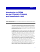
Chapter 1 Introduction to SPMA for the FRX4000, FRX6000, and SmartSwitch 1800 Using this Guide; manual conventions; contacting the Cabletron Systems’ Global Call Center; firmware versions supported by SPMA Your SPMA for the FRX4000, FRX6000, and the SmartSwitch 1800 management module provides management support for the FRX4000 stand-alone frame relay access device; its larger cousin, the FRX6000 scalable chassis; and the innovative SmartSwitch 1800 frame relay access device.
Introduction to SPMA for the FRX4000, FRX6000, and SmartSwitch 1800 NOTE The protocol support functions which are available via your SPMA application will vary depending on the protocol support you have purchased for your FRX or SmartSwitch 1800 device and the version of Þrmware you are running. For more information about available protocols and the current availability of SPMA support for those protocols, contact Cabletron SystemsÕ Global Call Center.
Introduction to SPMA for the FRX4000, FRX6000, and SmartSwitch 1800 disabling serial ports, and so on) available only from within the Hub View are also described. You can access the Hub View application from the icon menu or the command line. ¥ TIP Using this Guide Chapter 3, Trap Table, describes how to conÞgure the deviceÕs trap table, which controls which management stations will receive traps from a selected device. The Trap Table application is accessible from the Hub View.
Introduction to SPMA for the FRX4000, FRX6000, and SmartSwitch 1800 ¥ Chapter 12, SmartSwitch 1800 Voice ConÞguration, describes how to conÞgure the two voice ports on the SmartSwitch 1800 and provides statistical information about voice trafÞc being transmitted across those ports. ¥ Appendix A, FRX4000, FRX6000, and SmartSwitch 1800 MIB Components, lists the IETF and proprietary MIBs supported by these devices. What’s NOT in the FRX User’s Guide . . .
Introduction to SPMA for the FRX4000, FRX6000, and SmartSwitch 1800 Screen Displays SPMA runs under a variety of different operating systems and graphical user interfaces. To maintain a consistent presentation, screen displays in this and other SPMA guides show an OSF/Motif environment. If youÕre used to a different GUI, donÕt worry; the differences are minor.
Introduction to SPMA for the FRX4000, FRX6000, and SmartSwitch 1800 TIP The FRX Hub View application currently prints few footer messages (most of which relate to loss of contact with the device), so little information will typically be recorded in the History window; future releases will expand this feature. Figure 1-2. The History Window Using the Mouse The UNIX mouse has three buttons. Procedures within the SPMA document set refer to these buttons as follows: Button 1 Button 2 Button 3 Figure 1-3.
Introduction to SPMA for the FRX4000, FRX6000, and SmartSwitch 1800 If youÕre using a two-button mouse, donÕt worry. SPMA doesnÕt make use of mouse button 2. Just click the left button for button 1 and the right mouse button when instructed to use mouse button 3. Whenever possible, we will instruct you on which mouse button to employ; however, menu buttons within SPMA applications will operate according to the convention employed by the active windowing system.
Introduction to SPMA for the FRX4000, FRX6000, and SmartSwitch 1800 Modem Setting 8N1: 8 data bits, 1 stop bit, No parity For additional information about Cabletron Systems products, visit our World Wide Web site: http://www.cabletron.com/. For technical support, select Service and Support. FRX4000, FRX6000, and SmartSwitch 1800 Firmware SPMA for the FRX4000, FRX6000, and the SmartSwitch 1800 has been beta-tested against released Þrmware version 4.
Chapter 2 Using the FRX4000, FRX6000, and SmartSwitch 1800 Hub View Navigating through the Hub View; monitoring hub performance; managing the hub The heart of the SPECTRUM Portable Management Application (SPMA) for the FRX4000, FRX6000, and SmartSwitch 1800 is the Hub View, a graphical interface that gives you access to many of the functions that provide control over the selected FRX or SmartSwitch device and its installed interfaces.
Using the FRX4000, FRX6000, and SmartSwitch 1800 Hub View NOTES The spmarun script invoked Þrst in the above command temporarily sets the environment variables SPMA needs to operate; be sure to use this command any time you launch an application from the command line. This script is automatically invoked when you launch an application from the icon menu or from within the Hub View.
Using the FRX4000, FRX6000, and SmartSwitch 1800 Hub View Module Status LIC Name Port Status FRX6000 FRX4000 or SmartSwitch 1800 Figure 2-1. The FRX4000, FRX6000 and the SmartSwitch 1800 Hub Views NOTE LAN card indexing is determined simply by the order in which the installed LAN cards are identiÞed during the initial FRX6000 Þrmware installation. During the Þrmware installation, you will be prompted to enter the number of LAN cards you have installed, then prompted to supply their type.
Using the FRX4000, FRX6000, and SmartSwitch 1800 Hub View RLP information will only be displayed if the appropriate database record has been conÞgured via console management (see your hardware documentation for more information); for RLPs which have been conÞgured in the database but not yet installed in the chassis, a blue module status will be displayed (see Port and Module Color Codes, below). RLPs which are present in the chassis but which have not been conÞgured in the database will not be displayed.
Using the FRX4000, FRX6000, and SmartSwitch 1800 Hub View The module status color code indicates one of two conditions: if a module is both present in the chassis and conÞgured in the database, its index box will be color-coded green; if a module has been conÞgured in the database but is not physically present in the chassis, its index box will be color-coded blue. Modules which are physically present but not yet conÞgured in the database are not displayed at all in the Hub View.
Using the FRX4000, FRX6000, and SmartSwitch 1800 Hub View Using the Mouse in a Hub View Module For each RLP and LAN card displayed in the Hub View (that is, those which are at least conÞgured in the database), you can use the mouse to access various module- and port-level menus and functions, as illustrated below. When a LIC card is installed, the current Port Display Form selection is shown here; a value of [None] indicates that no LIC is present Figure 2-3.
Using the FRX4000, FRX6000, and SmartSwitch 1800 Hub View The Hub View Front Panel In addition to the graphical display of the RLP and LAN cards installed in your device and/or conÞgured in its database, the Hub View gives you device level summary information.
Using the FRX4000, FRX6000, and SmartSwitch 1800 Hub View IP Address The deviceÕs Internet Protocol address; this Þeld will display the IP address you have used to create the device icon (if you are running the Hub View from a management platform) or the IP address you used to launch the Hub View program (if you are running in stand-alone mode). You cannot change the IP address from within SPMA. TIP For FRX Þrmware versions 3.3.0, 3.3.1, and 4.0, each installed LAN card can be assigned an IP address.
Using the FRX4000, FRX6000, and SmartSwitch 1800 Hub View Clicking the Device button displays the Device menu, Figure 2-4. Figure 2-4. Hub View Device Menu The Device menu lets you perform the following: Using the Hub View ¥ Open the Device Information window (described in Viewing Device Information, page 2-16). ¥ Open the Polling Intervals window (described beginning on page 2-32). ¥ Select a Port Display Form (described beginning on page 2-12).
Using the FRX4000, FRX6000, and SmartSwitch 1800 Hub View ¥ Open the Frame Relay Backup Group window (described in Chapter 5, Frame Relay Status and ConÞguration). ¥ Open the IP, IPX, Bridge, and SNA conÞguration windows (described in Chapters 7, 9, 10 and 11). ¥ Open the Voice ConÞguration windows (described in Chapter 12, Voice ConÞguration).
Using the FRX4000, FRX6000, and SmartSwitch 1800 Hub View Frame Relay, X.25, LAN and Unconfigured Port Menus Device Menu LANCard and RLP Module Menus BSCI, Voice, and SDLC Port Menus Figure 2-5.
Using the FRX4000, FRX6000, and SmartSwitch 1800 Hub View Hub performance data available through these menus includes: TIP ¥ Device, Module, and Port conÞguration information. ¥ Generic Module and Port health and threshold statistics. ¥ Serial Port pin status. ¥ Protocol-speciÞc Port-level statistics. The health and protocol statistics are displayed via the SPMA Meters application; for more information on how to manipulate meters, see the SPMA Tools Guide.
Using the FRX4000, FRX6000, and SmartSwitch 1800 Hub View Admin Status The Admin Status port display form indicates the current value of the ifAdminStatus OID: UP the port has been administratively enabled DOWN the port has been administratively disabled TEST the port has been administratively placed in a test mode UNK unknown; device is returning a value that the software does not recognize --- the device is not responding.
Using the FRX4000, FRX6000, and SmartSwitch 1800 Hub View 2-14 disa (disabled) The port is operationally disabled. disc (disconnect) One of the two endpoints connected via the port has closed the connection. conf (conÞgured) The port has been conÞgured in the database, but the conÞgured protocol has not been installed on the associated RLP card.
Using the FRX4000, FRX6000, and SmartSwitch 1800 Hub View Connector Type This port display form indicates the connector type supported by the selected port. This value (from the OID nlIfConnectorType) is determined by a combination of cable and physical port type, as follows: rs232 Indicates an RS232 serial port, which must always use an RS232 cable. v35 Indicates a v.35 serial port, which must always use a v.35 cable. rs449 Indicates an RS422 serial port conÞgured for an RS449 cable.
Using the FRX4000, FRX6000, and SmartSwitch 1800 Hub View Viewing Device Information The Device Information window provides some general descriptive information about the FRX or SmartSwitch 1800 device you are modeling. To access the window: 1. In the Hub View, click on to display the Device menu. 2. Drag down to Device Information, and release. The Device Information window, Figure 2-6, will appear. Figure 2-6.
Using the FRX4000, FRX6000, and SmartSwitch 1800 Hub View Figure 2-7. The RLP ConÞguration Window and Protocol Menu RLP status information includes: Status A status of Installed indicates that the RLP is physically present in the chassis, and has been conÞgured in the database; a status of ConÞgured indicates that a database record has been conÞgured, but the card is not physically present in the hub. Memory Displays the amount of memory installed on the selected RLP, either 4 or 8 megabytes.
Using the FRX4000, FRX6000, and SmartSwitch 1800 Hub View NOTE You must have 8 megabytes of memory installed on at least one RLP in the FRX to run Þrmware version 4.0. If you have RLPs with only 4 megabytes of memory and want to upgrade them to 8 megabytes, contact CabletronÕs Global Call Center or your local service representative for more information. LIC 1 Type/LIC 2 Type Displays the type value for each Line Interface Card (LIC) installed on the selected RLP: RS232, HS RS232, v.
Using the FRX4000, FRX6000, and SmartSwitch 1800 Hub View ¥ If LLC2 is conÞgured, Bridge must also be conÞgured. For the FRX6000, both protocols should be, but do not have to be, on the same RLP. Having them on the same RLP should provide better performance. ¥ If NVSP is conÞgured, LLC2 and Bridge must also be conÞgured. For the FRX6000, all three protocols can be, but do not have to be, on the same RLP.
Using the FRX4000, FRX6000, and SmartSwitch 1800 Hub View Figure 2-8. The Port ConÞguration Window and Protocol Menu To change or add a protocol for the selected port: 1. Display the Configuration window for the selected port. It will display either a configured protocol or None. 2. To change a protocol, click on the menu button to display a list of options, then drag up or down to select the option you want. The Protocol menu will only list protocols that are supported on that RLP. 3.
Using the FRX4000, FRX6000, and SmartSwitch 1800 Hub View Interface Description: TIP Displays a general description of the selected serial interface (from the MIB II ifDescr), including the index number assigned to the portÕs RLP; the physical number assigned to the port interface itself (as designated in the Port Index box in the Hub View), and a general text description of the port, including the protocol currently conÞgured to run over that port.
Using the FRX4000, FRX6000, and SmartSwitch 1800 Hub View Figure 2-10. The Pin Status Window Each cable pin is represented by a colored rectangle labeled with the pin name; the color-coding tells you whether the pin is active (green; has voltage), inactive (red; has no voltage), unused (tan, or no color), or its electrical status is unknown (yellow). Each serial port provides information about the following pins: TD (transmit data) Pin will be active when the connection is operational.
Using the FRX4000, FRX6000, and SmartSwitch 1800 Hub View NOTE The pin names which end in ÒBÓ Ñ TDB, RDB, CTSB, DCDB, TCB, RCB, TTB, RTSB, and DSRB Ñ have the same deÞnitions as those listed above, but for the B channel signals used by V.35 and RS449 interfaces. Viewing LAN Port Information The LAN Port Information windows also provide general descriptive information about the selected port. To access LAN port information: 1.
Using the FRX4000, FRX6000, and SmartSwitch 1800 Hub View Address: TIP For Token Ring LAN cards, this Þeld displays the locally administered physical address, if one has been assigned; if none has been assigned, the Þeld (labeled Local Admin Address) will displays all zeros. For Ethernet cards, the factory-set physical address (labeled Physical Address) will be displayed.
Using the FRX4000, FRX6000, and SmartSwitch 1800 Hub View Figure 2-12. The RLP Health Statistics Window RLP Health statistics provide the following general usage information for all ports on the selected card: Frames Received The total number of frames received on all active serial ports on the selected RLP, expressed as a rate (frames/second). Frames Transmitted The total number of frames transmitted by all active serial ports on the selected RLP, expressed as a rate (frames/second).
Using the FRX4000, FRX6000, and SmartSwitch 1800 Hub View Frames Queued The total number of frames from all active serial ports on the selected RLP currently queued and waiting for transmission, expressed as a raw value. Queued frames will be transmitted as soon as device resources permit. Used Buffers Displays the percentage of available buffers currently being used by queued frames. Serial Port Health To access Serial Port Health statistics: 1.
Using the FRX4000, FRX6000, and SmartSwitch 1800 Hub View sequence (like the CRC, or cyclic redundancy check) is a value computed at both the sending and receiving ends of the connection; if the computed values donÕt match, the frame is assumed to have been corrupted in transit. A value consistently greater than zero indicates line problems.
Using the FRX4000, FRX6000, and SmartSwitch 1800 Hub View Figure 2-14. The LAN Health Statistics Window MIB II statistics provided are: 2-28 In Octets (ifInOctets) The total number of octets (or bytes) of data received at the selected LAN interface, expressed as a rate (octets/second). In Ucast (ifInUcastPkts) The total number of packets received at the selected LAN interface that were destined for a single address (unicast), expressed as a rate (packets/second).
Using the FRX4000, FRX6000, and SmartSwitch 1800 Hub View Out Ucast (ifOutUcastPkts) The total number of packets transmitted by the selected LAN interface that were destined for a single address (unicast), expressed as a rate (packets/second). Out NUcast (ifOutNUcastPkts) The total number of packets transmitted by the selected LAN interface that were destined for more than one address (either broadcast or multicast), expressed as a rate (packets/second).
Using the FRX4000, FRX6000, and SmartSwitch 1800 Hub View Figure 2-15. The RLP Statistics Thresholds Window The RLP Statistics Thresholds window shows the current threshold value (either a number or a percentage) for the following RLP health statistics (for deÞnitions of the RLP Health Statistics, see RLP Health, page 2-24): Percentage of Buffers in Use Shows the threshold for the Used Buffers statistic. Message Queue Length Shows the threshold for the Frames Queued statistic.
Using the FRX4000, FRX6000, and SmartSwitch 1800 Hub View 2. Drag down to Thresholds, and release. The Port Statistics Thresholds window, Figure 2-16, will appear. Figure 2-16.
Using the FRX4000, FRX6000, and SmartSwitch 1800 Hub View Receive Error Ratio Shows the threshold for the Receive Error Ratio statistic. This statistic is the ratio of frames rejected per second to frames accepted per second on the port. Transmit Percent Utilization Shows the threshold for the Tx Utilization % statistic. Receive Percent Utilization Shows the threshold for the Rx Utilization % statistic.
Using the FRX4000, FRX6000, and SmartSwitch 1800 Hub View 4. To change a polling interval, highlight the value you would like to change, and enter a new value in seconds. Note that the Use Defaults option must not be selected, or values will revert back to default levels when you click on , and your changes will be ignored. 5.
Using the FRX4000, FRX6000, and SmartSwitch 1800 Hub View Enabling and Disabling Serial Ports You can use the Port Menu available for each conÞgured serial port and LAN port to change the selected portÕs administrative status. To do so: 1. In the Hub View, click on the appropriate Port Index or Port Status text box to display the Port Menu (see Figure 2-3, page 2-6). 2. Drag down to Enable or Disable, as desired, and release.
Chapter 3 Configuring the Trap Table A few words about traps; accessing the Trap Table window; configuring the trap table About Traps The FRX4000, FRX6000, and the SmartSwitch 1800 have the ability to issue unsolicited SNMP traps to notify management stations of unusual events. These traps will not be issued, however, until the deviceÕs trap table has been properly conÞgured, designating one or more workstations to receive the traps and selecting the traps that will be sent.
Configuring the Trap Table Figure 3-1. The Trap Table The list box at the top of the window displays the trap table entries that have already been conÞgured; the Þelds and buttons in the lower portion of the window allow you to add new entries and modify or delete existing ones. Each device can support up to 16 entries in its trap table. Each trap table entry contains the following parameters: IP Address Indicates the IP address of the management workstation that will receive traps.
Configuring the Trap Table traps with a severity level equal to or greater than this severity setting will be forwarded to the associated management workstation. Each trap is assigned one of four severity levels: Informational Indicates an informational event (no action generally required) or a small conÞguration error. This is a Level 4 severity. Minor Indicates a minor fault or trafÞc disturbance; recommended action typically involves clearing the fault at the Þrst suitable occasion.
Configuring the Trap Table To delete an existing entry: 1. In the list box, click to select the entry you wish to delete. The selected entry will be highlighted. (Note that you can only delete one entry at a time.) 2. Click on to delete the selected entry.
Configuring the Trap Table SABM/DISC with wrong link address 198 The HDLC frame processor task for the port has received an improperly addressed frame from the subscriber. This situation usually occurs when the port and subscriber devices are both conÞgured as logical DCEs or logical DTEs. Severity Informational (Level 4) Action Modify the Port record so that one end of the connection is a logical DCE and the other is a logical DTE.
Configuring the Trap Table LP Trn Frm/Sec exceeded T: “n” C: “n” 307 The RLP statistic Transmitted Frames/Sec has exceeded the threshold (T: ÒnÓ) that was set by the user. (C: ÒnÓ is the current value.) Severity Informational (Level 4) Action If this happens frequently, you may need to reroute some trafÞc. LP Rej Frm/Sec exceeded T: “n” C: “n” 308 The RLP statistic Rejected Frames/Sec has exceeded the threshold (T: ÒnÓ) that was set by the user. (C: ÒnÓ is the current value.
Configuring the Trap Table FCS Rej/Sec exceeded T: “n” C: “n” 314 The port statistic FCS Errors/Sec has exceeded the threshold (T: ÒnÓ) that was set by the user. (C: ÒnÓ is the current value.) A value consistently greater than zero indicates line problems. Severity Informational (Level 4) Action If this happens frequently, check the line for noise, and check for conÞguration errors on both the FRX port and the connected user device.
Configuring the Trap Table Trn Port Usage exceeded T: “n” C: “n” 319 The port statistic % Transmit Port Utilization has exceeded the threshold (T: ÒnÓ) that was set by the user. (C: ÒnÓ is the current value.) Severity Informational (Level 4) Action If this happens frequently, you may need to add ports or reroute some trafÞc. Receive Yellow Alarm Condition Set A Yellow Alarm was received. Severity Major (Level 2) Action Contact your T1 carrier.
Configuring the Trap Table Link Disabled The port has been disabled from the On-Line Port Operations menu. Severity 401 Major (Level 2) Link Disconnected For X.25, this means that the link is disconnected and level 2 cannot be established. 402 For SNA TPAD, this means that an XID command frame has been issued by the TPAD, but either there has been no response or the received XID data does not match the XID data conÞgured for the TPAD subscriber.
Configuring the Trap Table Operational For all ports except those noted below, this means that the link is up. 406 For SNA TPAD, this means that the XID exchange has been performed, and the XID data received in the response frame matches the XID data conÞgured for the TPAD subscriber. The link is ready to establish an X.25 connection with the remote HPAD. For SNA HPAD, this means that an XID or SNRM command frame has been received for at least one of the link addresses conÞgured for the HPAD subscriber.
Configuring the Trap Table PAD Link Failed Self-explanatory. 413 Severity Major (Level 2) Action Check the async PAD port and its cables for proper operation and secure connection. Beginning of Congestion 414 The level of Maximum Congestion speciÞed in the Node Defaults record has been exceeded, and no more events will be put into the event buffer until the Minimum Congestion level (also speciÞed in the Node Defaults record) has been reached.
Configuring the Trap Table Duplicate of DLCI “n” on Port 428 Each connection sharing a DLCI must be on a different logical port, and two records have been conÞgured in the FRX specifying the same logical port on one DLCI. (DLCIs are conÞgured in records for logical ports, IP/LLC2/IPX interfaces over frame relay, and frame relay PVCs.) Only one of the duplicate connections will come up.
Configuring the Trap Table LG Buffer MALLOC Problem PKTs Lost 435 This applies to a debug tool used by service personnel, and will not appear under normal operation. Severity Major (Level 2) RCV Unknown Event Code from Net. An unknown event was received from the network. Severity Major (Level 2) RCV Invalid Event Format from Net. The node has received an event with an invalid format.
Configuring the Trap Table Port Config File Upd: PRTPAR.DAT The Port conÞguration Þle has been updated. Severity Informational (Level 4) Pad Profile File Upd: PROFILE.DAT The Async PAD ProÞle Þle has been updated. Severity 3-14 453 Informational (Level 4) Remote Update File Upd: UPDATE.TXT A software update has been sent. Severity 452 Informational (Level 4) Alarm Enable File Upd: ERRMSG.TXT The Alarms Þle has been updated. Severity 451 Informational (Level 4) X.25 Default File Upd: X25REC.
Configuring the Trap Table Login Password Changed Self-explanatory. Severity 455 Informational (Level 4) Operator Logged into Node 456 An async terminal operator has logged into the node via an async PAD port. Severity Informational (Level 4) Operator Logged out of Node 457 The async terminal operator has logged out of the node via the async PAD port. Severity Informational (Level 4) PAD Login File Upd: PADLOG.DAT The Login Þle has been updated.
Configuring the Trap Table LP Msg Queued Under Threshold The situation that caused event 305 has ended. Severity Informational (Level 4) LP Rcv Frm/Sec Under Threshold The situation that caused event 306 has ended. Severity 475 Informational (Level 4) Tran Err Ratio Under Threshold The situation that caused event 316 has ended. 3-16 474 Informational (Level 4) Log Rej/Sec Under Threshold The situation that caused event 315 has ended.
Configuring the Trap Table Severity Informational (Level 4) Rcv Err Ratio Under Threshold The situation that caused event 317 has ended. Severity Informational (Level 4) Port Rcv Usage Under Threshold The situation that caused event 318 has ended. Severity 478 Informational (Level 4) Port Trn Usage Under Threshold The situation that caused event 319 has ended.
Configuring the Trap Table Interface “n” deleted successfully Self-explanatory. Severity Informational (Level 4) Interface “n” added successfully Self-explanatory. Severity 486 Informational (Level 4) Interface “n” modified successfully Self-explanatory. Severity 485 487 Informational (Level 4) Error deleting route with destination “n,” mask “n,” router “n” Self-explanatory. Severity Minor (Level 3) Action Contact Cabletron SystemsÕ Global Call Center.
Configuring the Trap Table Alloc Error on Master SNMP Agent A buffer could not be allocated to process an SNMP message. Severity Critical (Level 1) BPAD: Invalid Q Pkt “n”—PL An invalid Q packet has been received, disabling the port. Severity Minor (Level 3) Action ConÞgure the LIC or remove it from the node. BPAD: Invalid Pkt “n”—PL An invalid packet has been received, disabling the port. Severity Minor (Level 3) Action Take the same action as for message 500.
Configuring the Trap Table BSCI: Invalid parameters 514 One or more parameters speciÞed in the Port Parameters record for this port is invalid. This error disables the port. Severity Minor (Level 3) Action Correct the Port Parameters record, then reenable the port ([B], [A], [C] from the Main Menu). If this doesnÕt work, take the same action as for message 500. BSCI: Invalid port number or type 515 The port number and/or type speciÞed in the Port record is not valid for BSC Interactive.
Configuring the Trap Table BSCI: Invalid queue operations An invalid operation has occurred and has disabled the port. Severity Minor (Level 3) Action Take the same action as for message 500. BSCI: Invalid protocol operations An invalid operation has occurred and has disabled the port. Severity Minor (Level 3) Action Take the same action as for message 500. BSCI: Invalid CUA, DUA operations An invalid operation has occurred and has disabled the port.
Configuring the Trap Table Exit Service Affecting Condition The situation that caused event 362 has ended. Severity Major (Level 2) DLCI “n” Frm Relay PVC Disconnected Self-explanatory. Severity 533 534 Informational (Level 4) DLCI “n” Received Bad Frame 535 Either the DLCI was not conÞgured or the frame was on an unavailable DLCI. Severity Minor (Level 3) Action ConÞgure the DLCI or resent the frame. DLCI “n” No Response to STATUS ENQ There was no response to a status enquiry from the DTE.
Configuring the Trap Table DLCI “n” Frame Relay Header Invalid The header contained an invalid DLCI. Severity Minor (Level 3) Action Check the conÞguration record for the port. DLCI “n” PVC does not exist Self-explanatory. Severity Minor (Level 3) Action Create a PVC record. 541 542 DLCI “n” Frame Discarded—CIR 543 A frame was discarded, probably because the excess burst size (BE) was exceeded. Severity Minor (Level 3) Action The frame must be resent.
Configuring the Trap Table LLC Host File Upd: LLC2HPAR.DAT The LLC2 Host Þle has been updated. Severity Informational (Level 4) LLC LAN Card File Upd: LANPAR.DAT The LLC2 LAN Card Þle has been updated. Severity 641 Informational (Level 4) IPX Interface File Upd: IPXISUB.DAT The IPX Interfaces Þle has been updated. Severity 640 Informational (Level 4) Bridge Filt App File Upd: BRGFLTAP.DAT The Bridge Filter Applications Þle has been updated.
Configuring the Trap Table Receive Loss of Sync condition Set 650 The receiving end of the connection has reported a loss of synchronization. Severity Major (Level 2) Action Check the T1/E1 cable at the local end of the connection. If it is securely connected and everything else appears operational, contact your carrier. Receive Carrier Loss condition Set 651 The receiving end of the connection has reported that the signal from the carrier is lost.
Configuring the Trap Table SDLC Rem. Link Stn Not Responding Self-explanatory. (Rem Link Stn is the Remote Link Station.) Severity Major (Level 2) Action Check the PU to make sure it is operational. 701 SDLC Link Stn Sent DM 702 The link station sent a Disconnect Mode response, and the logical link is down. Severity Major (Level 2) SDLC Link Stn rcvd FRMR, Inv. cmd 704 The remote device received an invalid command and responded with a Frame Reject.
Configuring the Trap Table SDLC Rem Stn Exceeded window size 711 The number of frames sent by the remote device has exceeded the window size. Severity Major (Level 2) SDLC Station Inactivity time exp 712 The timer deÞned by the parameters No Response Poll Period and Maximum Retransmissions in the SNA Port record has expired. Severity Major (Level 2) Action Check the PU to make sure it is operational.
Configuring the Trap Table SDLC No CTS on link A necessary CTS was not received from the DCE. Severity Major (Level 2) Action Check the modem to make sure it is operational. 721 SDLC No External Clock The necessary clock is not being provided. Severity Major (Level 2) Action Check the modem to make sure it is operational. 722 SDLC LLC/2 Remote Link Stn lost The remote station is not responding. Either the Inactivity Timer (Ti) or Acknowledgment Timer (T2) has expired.
Configuring the Trap Table LLC/2 FRMR Rcvd, IFLD too long 742 The remote device received an I frame that was too long, and returned a Frame Reject. Severity Major (Level 2) LLC/2 FRMR Rcvd, Invalid Command 743 The remote device received an invalid command or response, and returned a Frame Reject. Severity Major (Level 2) LLC/2 FRMR Sent, IFLD not permitted 744 The remote device sent an I frame when it was not permitted, and a Frame Reject was returned.
Configuring the Trap Table SDLC Link Stn rcv FRMR, Unexp. IFLD 762 The remote station received an S or U frame with an unexpected I frame attached.
Chapter 4 Configuring the Subscriber Table About the Subscriber Table and Subscriber IDs; accessing the Subscriber Table window; adding or modifying a subscriber table entry; editing the Routing and Address tables The Subscriber Table allows you to add or modify the entries your FRX or SmartSwitch 1800 will use to establish virtual connections to end-user devices in the network.
Configuring the Subscriber Table Accessing the Subscriber Table To launch the Subscriber Table: 1. In the Hub View, click on the button to display the Device menu. 2. Drag down to Subscriber Table, and release. The Subscriber Table window, Figure 4-1, will appear. Figure 4-1.
Configuring the Subscriber Table The Subscriber Table window contains three main areas: the Subscriber Table itself (in the top half of the window), which allows you to add, modify, or delete subscriber entries; the Routing Table (on the lower left), which allows you to assign one or more routing paths to a subscriber entry by associating that entry with one or more physical or logical ports on your device; and the Address Table (on the lower right), which allows you to assign the addresses that will be us
Configuring the Subscriber Table Algorithm The algorithm Þeld allows you to select the means by which call requests are forwarded to one of several routing paths assigned to the named subscriber. You can select from among four options: TIP Round Robin As its name implies, this algorithm selects ports cyclically in numeric order (as conÞgured in the Routing Table). If a selected port is unreachable or congested, call requests are forwarded on to the next port in sequence.
Configuring the Subscriber Table Priority The Connection Priority Þeld allows you to conÞgure priorities for trafÞc within the device: the higher the number assigned to the subscriber, the higher the priority that subscriberÕs calls will receive relative to other intra-nodal trafÞc. These priorities have no effect on trafÞc exiting the device.
Configuring the Subscriber Table Configuring Address Table Entries If you have selected any redirect parameters for a Subscriber Table entry, you must use the Address Table to designate the alternate subscriber addresses that will be used by the redirect option(s) you have selected (see page 4-4 for more information on redirect options). You can designate up to Þve alternate addresses for each subscriber table entry.
Configuring the Subscriber Table c. Click Yes on the Systematic Redirect option if you wish all calls to this subscriber to be redirected to the first alternate address defined in the Address Table. If you select this option, no calls will be received by the original subscriber, and only the first alternate subscriber will be used. Select No if you do not wish to redirect calls in this way. d.
Configuring the Subscriber Table 4. In the Address Table: a. If you wish to modify an existing Address Table entry, be sure that entry is selected (and remember, any changes you make to the Address Table effect the Subscriber Table entry currently highlighted in the top portion of the window). b. In the Index field, enter the index value you wish to assign to the entry you are configuring. Allowable values are 1-5; these values need not be assigned sequentially. c.
Chapter 5 Frame Relay Status and Configuration About using the frame relay protocol; frame relay port and DLCI rate configuration; configuring frame relay backup groups; logical port configuration; viewing frame relay management, congestion, and error stats FRX and SmartSwitch 1800 ports which have been conÞgured to use frame relay as their layer 2 protocol can be used to carry both frame relay trafÞc and trafÞc from other protocols which has been encapsulated in frame relay (per RFC 1490).
Frame Relay Status and Configuration ¥ Frame Relay Management Stats provide an overview of the frame management (LMI or Annex D) in use on the selected port, displayed via meters; ¥ Frame Relay Congestion Stats provide information about congestion notiÞcation and discard eligibility frames being transmitted across the port, also displayed in meters; and ¥ The Frame Relay Errors window provides a single meter, which displays the current frame discard rate.
Frame Relay Status and Configuration Figure 5-1. Frame Relay Port ConÞguration The Frame Relay ConÞguration window provides the following information: Max Bytes per Frame This Þeld speciÞes the size (in bytes) of the largest frame that can be transmitted across the port. This value is determined by your frame relay service provider. Line Speed This Þeld speciÞes the data transmission rate in bits per second.
Frame Relay Status and Configuration Possible line speed entries are: 75 150 300 600 1200 2400 4800 9600 14400 19200 24000 28800 38400 48000 56000 64000 72000 112000 128000 168000 192000 224000 256000 280000 320000 336000 384000 392000 448000 504000 512000 560000 576000 616000 640000 672000 704000 728000 768000 784000 832000 840000 896000 952000 960000 1008000 1024000 1064000 1088000 1120000 1152000 1176000 1216000 1232000 1280000 1288000 1344000 1400000 1408000 1456000 1472000 1512000 1536000 1568000
Frame Relay Status and Configuration N3 Monitored Events Count The monitored events count deÞnes the number of error-free polling cycles that must occur before the DCE is declared active if the Þrst poll resulted in an error. If the Þrst poll is error-free, the DCE is declared active immediately. If the N2 Error Threshold is exceeded during the N3 count, the DCE will be declared inactive, and the N3 count will be restarted.
Frame Relay Status and Configuration ¥ For the FRX6000, ports 0-7 on each RLP are determined by the Line Interface Card (LIC) and attached I/O cables. Only the valid interfaces will be listed from the menu button. Possible interfaces are: RS-232, V.35, RS-449, RS-530 and X.21. (RS-449, RS-530, and X.21 interfaces require an RS-422 LIC.) Blocked Flag This value will cause the port to be enabled (if No) or disabled (if Yes) when the device is powered up or re-booted.
Frame Relay Status and Configuration links from becoming operational unless all DLCI rate settings match at both ends of the connection; without LMI, mismatched links may become operational, but they will behave unpredictably. LMI rev 1 enquiries from the Local Management Interface (LMI) will be used; ansiT1 617 D enquiries in ANSI T1.617 Annex D format (an ANSI standard LMI) will be used.
Frame Relay Status and Configuration Changing Configuration Values You can edit the values in any Þeld; to do so: 1. To edit a text field, remove the existing value and enter the new value. 2. To edit a field with a menu button, click on the button to display a list of options, then drag down to select the option you want. If you have made changes to the fields but would like to revert back to the previous values, click on the Refresh button. 3. Click on to save your changes.
Frame Relay Status and Configuration Figure 5-2. Frame Relay DLCI Table The Frame Relay DLCI Table window allows you to conÞgure the following parameters for each DLCI: NOTE In the DLCI Table you can conÞgure Primary and Backup DLCIs. If you are conÞguring a primary DLCI, there are six additional parameters that can only be conÞgured through console management. They are: Remote RLP, Remote Port, Remote DLCI, Switchover Timer, Switchback Timer, and Time to Hold Data While Waiting.
Frame Relay Status and Configuration above the deÞned CIR can be marked as discard eligible (DE); frames with the DE bit set are considered to be excess data, and will be discarded if the network becomes congested. TIP If congestion occurs on the selected DLCI while throughput is greater than the CIR, and the Outgoing Rate Control parameter (settable via the Frame Relay Port ConÞguration window, described beginning on page 5-2) is set to Yes, the throughput will immediately drop to the CIR level.
Frame Relay Status and Configuration Priority The Outgoing DLCI Priority value allows you to assign relative priority levels to the DLCIs conÞgured on the selected physical port. The allowable range is 0-4, with 0 being the lowest priority. Backup Group Number Use this Þeld to specify whether this DLCI is a primary or a backup DLCI. If it is a primary DLCI, enter the number (1-255) that identiÞes the Frame Relay Backup Group that will take over if this DLCI fails. If it is a backup DLCI, enter 0.
Frame Relay Status and Configuration 3. Click on to create a new entry, or on currently selected in the list box. to edit the entry Applying Port-level Changes After you have made any port-level conÞguration changes, your changes will not take effect until you have done an on-line update. To do so: 1. Click mouse button 3 on the port you have been configuring to display the Port Menu. 2. Drag down to On-line Update and release.
Frame Relay Status and Configuration parameters can be conÞgured, except specifying a Backup Group Number for the primary DLCI on the initiating node. The next step is to conÞgure your Backup Groups using the information in this section. You can then return to your DLCI conÞguration and enter the appropriate Backup Group Number that will assign a backup group to each primary DLCI. Configuring Frame Relay Backup Groups Use the Frame Relay Backup Groups window to conÞgure backup groups.
Frame Relay Status and Configuration RLP Indicates the RLP where the physical port on which the backup DLCI is being conÞgured resides. For the FRX4000 and SmartSwitch 1800 this would always be 0. For the FRX6000 this could be RLP 0 - 7. Port Indicates the physical port on which the backup DLCI is being conÞgured. DLCI This is the DLCI number of the backup being conÞgured.
Frame Relay Status and Configuration 3. Click on to create a new entry, or on currently selected in the list box. NOTE to edit the entry After you have made system-level changes (such as conÞguring Frame Relay Backup Groups), you must apply those changes by rebooting the FRX or SmartSwitch 1800 device, or through console management via the [F7] command.
Frame Relay Status and Configuration Figure 5-4. Logical Port ConÞguration The Logical Port ConÞguration window allows you to conÞgure the following parameters: Logical Port This Þeld speciÞes the number of the logical port being conÞgured. Valid entries are 8 - 63. DLCI Number Use this Þeld to enter the Data Link Connection IdentiÞer (DLCI), a routing ID that links the logical port to a virtual connection on the physical frame relay port. This number is usually assigned by your frame relay provider.
Frame Relay Status and Configuration You must conÞgure a different DLCI for every logical port on a physical port because logical ports and DLCIs have a one-to-one relationship. Also, make sure that each interface (IP, IPX or LLC2) or frame relay bridge port has a different DLCI. Do not assign a DLCI number that is conÞgured as a frame relay backup DLCI. Priority This Þeld allows you to set a priority for trafÞc within the node.
Frame Relay Status and Configuration Max UnACK Packets/Channel This speciÞes the maximum number of sequentially numbered frames that can be waiting for acknowledgment by the destination device. If this number is exceeded, no frames will be transmitted until an acknowledgment is received. Setup Packet Window Size This speciÞes a default window size that will be assigned to an incoming call setup packet if the packet does not include a window size. Valid values are 1 to 7 packets.
Frame Relay Status and Configuration Make Calls Outside CUG This Þeld is only conÞgurable if the port is a CUG member; it speciÞes whether the logical port can make calls to network users outside that CUG. Encapsulation Method This Þeld speciÞes whether the trafÞc will be encapsulated by Annex G or RS 1490 for transmission across the frame relay network. With Annex G, an LAPB frame is encapsulated immediately following the frame relay header (ßag, 2-byte T1.
Frame Relay Status and Configuration Accept Reverse Charge This Þeld is used to authorize the transmission of incoming calls that request Reverse Charging. If Yes is selected, a call requesting Reverse Charging will be accepted. If No is selected, and a call requests Reverse Charging, the call will not be transmitted. Fast Select This Þeld authorizes transmission of incoming calls that request the X.25 Fast Select facility. In Call Bar This is an X.
Frame Relay Status and Configuration TIP The statistical windows display their information via the SPMA Meters application; for more information on how to manipulate and conÞgure these meters, see the SPMA Tools Guide. Management Stats The Management Statistics window provides general information about the type of management trafÞc that is being transmitted across the selected port. To access the window: 1. Click mouse button 3 on the frame relay port of interest to display the Port Menu. 2.
Frame Relay Status and Configuration TIP You can select the type of management frames that will be transmitted across a selected port by conÞguring the Link Layer Management option in the Frame Relay Port ConÞguration window, described beginning on page 5-2. Congestion Stats The Congestion Statistics window provides information about the rates at which Discard Eligible and Congestion NotiÞcation frames are being both received and transmitted. To access the window: 1.
Frame Relay Status and Configuration BECN (Transmitted and Received) Displays the number of frames with the BECN (backward explicit congestion notiÞcation) bit set that were transmitted or received on the selected port, expressed as a rate (frames/second). BECN frames notify the user that trafÞc sent in the opposite direction to the received frame may encounter a congested path; this alerts the device to reduce inbound trafÞc.
Frame Relay Status and Configuration 5-24 Viewing Frame Relay Status
Chapter 6 X.25 Status and Configuration About using the X.25 protocol; configuring X.25 ports; viewing X.25 management, congestion, and error stats An FRX or SmartSwitch 1800 port conÞgured to run X.25 as its layer 2 protocol can connect to an X.25 DTE or an X.25 network. This allows the port to transmit X.25 trafÞc, as well as IP and IPX trafÞc (encapsulated as per RFC 1356) and SNA trafÞc. For any FRX or SmartSwitch 1800 physical ports which have been conÞgured to use X.
X.25 Status and Configuration NOTE Note that a frame relay port can support encapsulated X.25 trafÞc on a logical port. For information on logical ports, see Chapter 5. Configuring X.25 Physical Ports The X.25 Physical Port ConÞguration window allows you to set X.25 operational parameters for physical ports. To access the window: 1. Click mouse button 3 on the X.25 port of interest to display the Port Menu. 2. Drag down to X.25 Physical Port Configuration, and release. The X.
X.25 Status and Configuration The X.25 Physical Port ConÞguration window provides the following conÞguration information: Speed This Þeld speciÞes the data transmission rate in bits per second. If this port is a physical DTE, specify the line speed that matches the speed of the device connected directly to the port. If the port is a physical DCE (i.e., the attached I/O cable is DCE) specify the clock speed of the serial port you are conÞguring.
X.25 Status and Configuration Setup Timer The Setup Timer only has a function if the port you are conÞguring is a dial port; that is, if the port is connected to a dial modem. The setup timer starts when the port enters the linkup state. Use this Þeld to enter a time period (in seconds). If there is no response from the other end before the time period expires, the port will enter the failed state.
X.25 Status and Configuration NOTE Closed User Groups (CUG) are conÞgured using console management. Refer to your FRX or SmartSwitch 1800 hardware documentation for more information about CUGs Closed User Group Index This Þeld is only conÞgurable if the port is a CUG member; it speciÞes which Closed User Group the port belongs to. The CUG index number is included in call packets, and is cross-referenced with the CUG Index created through console management.
X.25 Status and Configuration Dial In/Out This parameter only has a function if the port you are conÞguring is a dial port; that is, if the port is connected to a dial modem. It speciÞes whether this port is connected to a dial modem and, if so, whether connections will be initiated through dial-in or dial-out calls. (Signaling differences prevent conÞguration for both dial-in and dial-out on the same port.) A port speciÞed as Dial Out will establish a link only when an outgoing X.
X.25 Status and Configuration Flow Control Negotiation This Þeld allows for negotiation of ßow control parameters (packet and window sizes for data transmission in either direction) on a per-call basis. If No is selected, the Default Packet Size and Setup Packet Window Size will be used. If Yes is selected, a packet and/or window size included in a call packet will be used. (If a packet and/or window size is not included, the default values will be used.
X.25 Status and Configuration Changing Configuration Values You can edit the values in any Þeld which provides a text box or menu button selection; to do so: 1. To edit a text field, remove the existing value and enter the new value. 2. To edit a field with a menu button, click on the button to display a list of options, then drag down to select the option you want. If you have made changes to the fields but would like to revert back to the previous values, click on the Refresh button. 3.
X.25 Status and Configuration Figure 6-2. X.25 Management Stats The Management Statistics window provides the following statistical data: SABM (Transmitted/Received) A count of the Set Asynchronous Balanced Mode (SABM) commands transmitted or received across the selected port, expressed as a rate (commands/second). UA (Transmitted/Received) A count of the Un-numbered Acknowledgment (UA) responses transmitted or received across the selected port, expressed as a rate (responses/second).
X.25 Status and Configuration 2. Drag down to X25 Congestion Stats, and release. The X25 Congestion Statistics window, Figure 6-3, will appear. Figure 6-3. X.25 Congestion Stats The Congestion Statistics window provides the following statistical data: INFO (Transmitted/Received) A count of the Information Transfer (INFO) commands transmitted or received across the selected port, expressed as a rate (commands/second).
X.25 Status and Configuration Figure 6-4. X.25 Error Stats The Error Statistics window provides the following statistical data: FRMR (Transmitted/Received) A count of the Frame Reject (FRMR) responses transmitted or received on the selected port, expressed as a rate (responses/second). Rej (Transmitted/Received) A count of the Reject (Rej) supervisory commands or responses transmitted or received on the selected port, expressed as a rate (commands or responses/second). Viewing X.
X.25 Status and Configuration 6-12 Viewing X.
Chapter 7 SNA Status and Configuration Configuring SNA ports; physical unit and LLC2 parameter configuration; configuring link stations; configuring LLC2 hosts; viewing statistics SNA ports in the FRX4000, FRX6000, and SmartSwitch 1800 connect IBM hosts with PUs (physical units), over a frame relay (via RFC 1490) or X.25 (via Annex G) network. SNA support includes SDLC (Synchronous Data Link Control) for serial lines and LLC2 (Logical Link Control type 2) for LAN connections.
SNA Status and Configuration In addition, for each SNA port there are four statistical windows provided: ¥ The SDLC Port Stats providing general port statistics; ¥ The SDLC LS General Stats providing link station statistics; ¥ The SDLC LS Rx Stats providing link station receive statistics; ¥ The SDLC LS Tx Stats providing link station transmit statistics. These windows and their functions are described in the following sections.
SNA Status and Configuration Figure 7-1. SDLC Port ConÞguration The SDLC Port ConÞguration window provides the following information: Packet Size This Þeld speciÞes the maximum packet size (in bytes) that will be transmitted on the port. The default value for this parameter is 1024. Line Speed This Þeld speciÞes the data transmission rate in bits per second. If this port is a physical DTE, specify the line speed that matches the speed of the device connected directly to the port.
SNA Status and Configuration Possible line speed entries are: 75 150 300 600 1200 2400 4800 9600 14400 19200 24000 28800 38400 48000 56000 64000 72000 112000 128000 168000 192000 224000 256000 280000 320000 336000 384000 392000 448000 504000 512000 560000 576000 616000 640000 672000 704000 728000 768000 784000 832000 840000 896000 952000 960000 1008000 1024000 1064000 1088000 1120000 1152000 1176000 1216000 1232000 1280000 1288000 1344000 1400000 1408000 1456000 1472000 1512000 1536000 1568000 1600000
SNA Status and Configuration ¥ For the SmartSwitch 1800, ports 2 and 3 are determined by the attached cables: RS-232, V.35, or RS-449; ¥ For the FRX4000, ports 4-7 are determined by the expansion Line Interface Card (LIC) and attached I/O cables. Only the valid interfaces will be listed from the menu button. Possible interfaces are: RS-232, V.35, RS-449, and X.21. (RS-449 and X.21 interfaces require an RS-422 LIC.
SNA Status and Configuration Receive Clock from DTE This parameter is relevant only if the Physical Port Interface (see above) is something other than RS-232 and Generate Clock is set to Yes. If this parameter is set to Yes, it allows the clock (timing) signal to be looped back from the DTE using the Terminal Timing (TT) signal, which can be helpful on high-speed lines.
SNA Status and Configuration Changing Configuration Values You can edit the values in any Þeld; to do so: 1. To edit a text field, remove the existing value and enter the new value. 2. To edit a field with a menu button, click on the button to display a list of options, then drag down to select the option you want. If you have made changes to the fields but would like to revert back to the previous values, click on the Refresh button. 3. Click on to save your changes.
SNA Status and Configuration Figure 7-2. SDLC Physical Unit Subscriber Table The SDLC Physical Unit Subscriber Table allows you to conÞgure the following parameters: NOTE An SNA TPAD subscriber can specify only one remote device, which can be an HPAD or an X.25 connection to the host. An HPAD subscriber can specify up to 16 remote devices, any of which can be a TPAD or an X.25 connection to the host. An XPAD subscriber can specify only one remote device, which must be another XPAD.
SNA Status and Configuration Remote Subscriber Id This is the subscriber address of the remote end of a SNA connection. It is used by the local device to identify where a call is going. Enter a Subscriber ID of up to 15 digits. A Subscriber ID record must also be conÞgured for this address (see Chapter 4, ConÞguring the Subscriber Table for Subscriber ID conventions).
SNA Status and Configuration Changing SDLC PU Subscriber Values To edit the values assigned to each SDLC PU Subscriber: 1. If you wish to modify an existing entry, be sure that entry is highlighted in the list box portion of the window. 2. Enter and/or edit the values displayed in the text boxes, as desired. (Remember, some values which are settable from this window must mirror values configured elsewhere; be sure these values match as necessary.) 3.
SNA Status and Configuration Figure 7-3. SDLC LLC2 ConÞguration window The SDLC LLC2 ConÞguration window allows you to conÞgure the following parameters: Address This is the SDLC PU Station Address, 00 - ff, that identiÞes the PU you are conÞguring. It must match the ADDR parameter set in the macro PU in the VTAM conÞguration. Local SAP Address This is the remote service access point (SAP) address used to connect the PU to the host.
SNA Status and Configuration IDBLK This parameter is used in conjunction with the IDNUM parameter (see below) in generating the Node Þeld in an XID (Exchange IdentiÞcation) frame (format 0 or 3) to establish a link station connection to the host. If both IDBLK and IDNUM are set to 0, the Node Þeld of the XID frame will be provided by the attached SDLC device. The node will send an XID command to the remote node to indicate that the SDLC device should be polled for an XID.
SNA Status and Configuration If the T1 Timer expires and acknowledgments or responses are still outstanding, the link station will send one of the following, then restart the T1 Timer: ¥ A Supervisory LPDU with the P bit set to BÕ1Õ to solicit remote link station status ¥ Any Unnumbered LPDUs that were not responded to the Þrst time they were sent.
SNA Status and Configuration BAGs regulate bandwidth usage by outgoing trafÞc on the physical link and can ensure that response time-sensitive trafÞc gets access to the available frame relay bandwidth. Up to 16 groups can be conÞgured through console management (refer to your FRX or SmartSwitch 1800 hardware documentation for more information).
SNA Status and Configuration Applying Port-level Changes After you have made any port-level conÞguration changes, your changes will not take effect until you have done an on-line update. To do so: 1. Click mouse button 3 on the port you have been configuring to display the Port Menu. 2. Drag down to On-line Update and release. SDLC Link Station Configuration You can use the SDLC Link Station ConÞguration window to conÞgure SDLC link station entries. To access the window: 1.
SNA Status and Configuration The SDLC Link Station ConÞguration window allows you to conÞgure the following parameters: Address This is the SDLC PU Station Address, 00 - ff, that identiÞes the PU you are conÞguring. It must match the ADDR parameter set in the macro PU in the VTAM conÞguration. Name Enter the name of the local SDLC link station. Max RX PDU Size This is the maximum PDU size that the local link station can receive from the adjacent link station.
SNA Status and Configuration Retry Sequence Repeat Count This Þeld speciÞes the number of times a retry sequence will be repeated for the local SDLC link station. The default value for this parameter is 0. RNR Limit This speciÞes the length of time (in 1/100ths of a second) an SDLC link station will allow its adjacent link station to remain in a busy (RNR) state before declaring it inoperative. A value of 0 means there is no limit. The default value for this parameter is 18000.
SNA Status and Configuration Changing SDLC Link Station Values To edit the SDLC Link Station values: 1. If you wish to modify an existing entry, be sure that entry is highlighted in the list box portion of the window. 2. Enter and/or edit the values displayed in the text boxes, as desired. (Remember, some values which are settable from this window must mirror values configured elsewhere; be sure these values match as necessary.) 3. Click on to create a new entry, or on currently selected in the list box.
SNA Status and Configuration 2. Drag down to SNA/LLC2 Hosts Table, and release. The SNA/LLC2 Host Table, Figure 7-5, will appear. Figure 7-5. The SNA/LLC2 Host Table The list box at the top of the window displays the LLC2 hosts that have already been conÞgured. It lists the hostsÕ MAC addresses and identiÞes each LLC2 session as Originated or Terminated. In an Originated session, the host initiates LLC2 sessions; in a Terminated session, the host accepts sessions destined for the address.
SNA Status and Configuration Session Type If you select Originated, the FRX or SmartSwitch 1800 will initiate LLC2 sessions from the conÞgured Host MAC Address. If Terminated, the node will accept LLC2 sessions destined for the conÞgured Host MAC Address. A host address can be conÞgured for one Originated and one Terminated session, but no more than one each. The default value for this parameter is Terminated.
SNA Status and Configuration T1-Reply Timer The Reply Timer is used to by the local node to detect a failure by the remote station to send a required acknowledgment or response. The local node will start the timer when it transmits either an Information LPDU or a Command LPDU with the P bit set to BÕ1Õ. (If the LPDU is sent while the timer is already running, the local node will reset the timer.
SNA Status and Configuration The value is the amount of time in milliseconds; the default value is 100. The value must be less than the value for the T1-Reply Timer (see above) to ensure that the remote link station will receive the delayed acknowledgment before the T1 Timer expires. Ti-Inactivity Timer This timer is used by the local node to detect an inoperative condition in either the remote link station or the transmission medium.
SNA Status and Configuration TIP When conÞguring priorities, be sure to consider the types of trafÞc being routed on other connections in the node. Routing Subscriber ID This Þeld associates a Subscriber ID with the LLC2 host. Enter a number up to 15 digits. An asterisk wildcard can be used as a Þnal digit (but the ? wildcard is not valid). If fewer than 15 digits are entered, an asterisk must be the Þnal character.
SNA Status and Configuration NOTE After you have made system-level changes (such as conÞguring LLC2), you must apply those changes by rebooting the FRX or SmartSwitch 1800 device, or through console management via the [F7] command. Configuring LLC2 Host Connections You can conÞgure the connections for each LLC2 Host by using the Originated or Terminated Connections Table. To access the Connections Table: 1. In the SNA/LLC2 Host Table, highlight the host whose connections you wish to configure. 2.
SNA Status and Configuration The list box at the top of the window displays any connections that have already been conÞgured.The Þelds and buttons in the lower portion of the window allow you to add new entries, and modify or delete existing ones. The Connections Table allows you to conÞgure the following parameters: Sequence This is simply a sequence number to allow selection of a line in the display. HSAP This is the host service access point (HSAP) address used to connect to the host.
SNA Status and Configuration Changing Host Connections To edit the Host Connection values: 1. If you wish to modify an existing entry, be sure that entry is highlighted in the list box portion of the window. 2. Enter and/or edit the values displayed in the text boxes, as desired. (Remember, some values which are settable from this window must mirror values configured elsewhere; be sure these values match as necessary.) 3. Click on to create a new entry, or on currently selected in the list box.
SNA Status and Configuration Figure 7-7. SDLC Port Statistics The SDLC Port Statistics window provides the following statistical data: Invalid LS Addr The number of frames received by this port with invalid link station (LS) addresses, expressed as a rate (frames/second). Dwarf Frames (Received) The number of frames received by this port which were delivered intact by the physical layer, but were too short to be legal.
SNA Status and Configuration Local Re-Tx I-Frames The number of I-frames retransmitted by all local SDLC link stations on this port, expressed as a rate (frames/second). Remote Re-Tx I-Frames The number of I-frames retransmitted by remote link stations for all SDLC link stations on this port, expressed as a rate (frames/second). Polls (Received and Transmitted) The number of polls received or sent by this port since the port was created, expressed as a rate (polls/second).
SNA Status and Configuration SDLC Link Station General Statistics The SDLC Link Station General Statistics window provides general information about the link station trafÞc that is being transmitted across the selected port. To access the window: 1. Click mouse button 3 on the SNA port of interest to display the Port Menu. 2. Drag down to SDLC LS General Stats, and release. The SDLC Link Station General Statistics window, Figure 7-8, will appear. Figure 7-8.
SNA Status and Configuration RNR Limits The number of times, since link station startup, when this SDLC link station has deactivated the link as a result of its RNR Limit Timer expiring, expressed as a rate (deactivations/second). Retries Exp The number of times, since link station startup, when this SDLC link station has deactivated the link as a result of a retry sequence being exhausted, expressed as a rate (deactivations/second).
SNA Status and Configuration The SDLC Link Station Rx and Tx Statistics window provides the following statistical data: BLU The total Basic Link Units (BLU) received from or transmitted to an adjacent SDLC link station since link station startup, expressed as a rate (BLUs/second). Poll The total number of polls received from or transmitted to an adjacent SDLC link station since link station startup, expressed as a rate (polls/second).
SNA Status and Configuration RIM The total number of Request Initialization Mode (RIM) frames received from or transmitted to an adjacent SDLC link station since link station startup, expressed as a rate (RIM frames/second). DISC The total number of Disconnect (DISC) requests received from or transmitted to an adjacent SDLC link station since link station startup, expressed as a rate (DISCs/second).
Chapter 8 BSC Interactive Configuration Configuring BSC Interactive ports; BSCI Subscriber Information; configuring devices connected to BSCI ports FRX4000, FRX6000, and SmartSwitch 1800 devices support binary synchronous communications (BSC) Interactive ports, used to connect IBM 3270 hosts to remote control units (CU) over frame relay or X.25.
BSC Interactive Configuration Figure 8-1. BSCI Port ConÞguration The BSCI Port ConÞguration window allows you to conÞgure the following parameters: Max Frame Size Use this Þeld to specify the maximum frame size that will be allowed to pass through this BSCI port. The default value for this parameter is 4105.
BSC Interactive Configuration Line Speed This Þeld speciÞes the data transmission rate in bits per second. If this port is a physical DTE, specify the line speed that matches the speed of the device connected directly to the port. If the port is a physical DCE (i.e., the attached I/O cable is DCE) specify the clock speed of the serial port you are conÞguring. Valid values for this parameter are: 75, 150, 300, 600, 1200, 2400, 4800, 9600, 14400, and 19200. The default value for this parameter is 9600.
BSC Interactive Configuration Error Retransmit Count This Þeld speciÞes the number of times the FRX or SmartSwitch 1800 will resend a block of data after the receiving device has detected an error in the block. The default value for this parameter is 5. NAK Retry Count This count speciÞes the number of times the FRX or SmartSwitch 1800 will send a frame when the receiving device is returning a NAK (negative acknowledgment).
BSC Interactive Configuration End-to-End ACK This read-only parameter is set to No, and indicates that management of acknowledgments will be handled locally at each end, rather than end-to-end across the network. Full Duplex This read-only parameter is set to Yes, and speciÞes full-duplex transmission.
BSC Interactive Configuration Generally, if the local interface is a physical DCE and the line speed is above 256 Kbps, this parameter should be set to Yes; however, make sure the DTE is conÞgured to provide the terminal timing. The default value for this parameter is No. Clear VC on Last Dev Down If Yes is selected, this parameter causes the virtual circuit to be cleared when no terminals are using it. The default value for this parameter is No.
BSC Interactive Configuration BSCI Subscriber ID Information The BSCI Subscriber Information window provides information on local and remote subscribers for each BSCI port. A local TPAD subscriber can specify only one remote device, which can be an HPAD or an X.25 connection to the host. A local HPAD subscriber can specify up to 16 remote devices, any of which can be a TPAD or an X.25 connection to the host. Each connection must be assigned a different local subscriber address.
BSC Interactive Configuration The top part of the window displays a list of BSCI port subscribers. The bottom part of the window allows you to modify or add the following BSCI subscriber information: Local Subscriber ID This is the subscriber address of the local end of a BSCI connection. Enter a Subscriber ID of up to 15 digits. This is the same subscriber ID that is speciÞed in the Subscriber Table (see Chapter 4, ConÞguring the Subscriber Table, for Subscriber ID conventions).
BSC Interactive Configuration Adding or Modifying BSCI Subscriber Information To add a new BSCI Subscriber entry: 1. Enter the Local Subscriber ID, the Remote Subscriber ID, and the other configurable parameters for the entry. 2. Click on to add your new entry. To modify an existing entry: 1. In the list box, click to select the Subscriber entry you wish to modify. The selected entry will be highlighted. (Note that you can only modify one entry at a time.) 2. Edit the fields, as desired.
BSC Interactive Configuration Figure 8-3. BSCI Device Information The top part of the window displays a list of conÞgured BSCI devices. The bottom part of the window allows you to modify or add the following BSCI device information: Control Unit ID This ID is a number 0 through 31 and identiÞes the control unit. Device Unit ID Enter a number, 0 through 31. Up to 32 Device Units can be conÞgured for each Control Unit.
BSC Interactive Configuration Transparent Text Support If Yes is selected, then all transmitted characters, including control character sequences, are treated as data. This parameter is useful for transmitting binary data and machine language computer programs without special coding. Data-link control character sequences transmitted this way must be preceded by a Data Link Escape (DLE) character (a value of 10 in hex) in order to be recognized as control characters.
BSC Interactive Configuration 8-12 Configuring BSCI Devices
Chapter 9 IP Interface Configuration Configuring IP Node Defaults; IP Interface configuration; Secondary Address configuration The FRX4000, FRX6000, and the SmartSwitch 1800 support dynamic routing of IP (internet protocol) trafÞc among IP devices on LANs and routed subnetworks, via frame relay or X.25. The FRX and SmartSwitch 1800 can also be conÞgured to act as IP gateways, forwarding IP packets they receive.
IP Interface Configuration Figure 9-1. The IP Node Window 3. Use the menu button to select the RIP version you want. 4. Click on NOTE to save your selection. After you have made system-level changes (such as conÞguring IP Node Defaults), you must apply those changes by rebooting the FRX or SmartSwitch 1800 device, or through console management via the [F7] command. Configuring IP Interfaces An IP interface allows the Internet Protocol to be executed over a frame relay, X.
IP Interface Configuration Figure 9-2. The IP Interface ConÞguration Window The list box at the top of the window displays the IP interfaces that have already been conÞgured; the Þelds and buttons in the lower portion of the window allow you to add new entries, and modify or delete existing ones. Following is a description of the IP Interface parameters. The parameters you will conÞgure for each interface depends on the IP Interface Type you select (see IP Interface Type deÞnition below).
IP Interface Configuration IP Interface Type In this Þeld, use the menu button to select the type of interface you wish to conÞgure. This selection will change the parameters that appear in the IP Interface ConÞguration window. Depending on your selection, certain parameters will be conÞgurable, and others will be grayed out. There are Þve IP interface types that you can select from: ¥ ¥ ¥ ¥ ¥ NOTE Rfc 877x25 (X.
IP Interface Configuration ICMP Add Routes Select Yes or No to specify whether IP may add routes obtained by ICMP (Internet Control Message Protocol). ICMPÕs error and control function is used to send redirection options back to the source, if problems are discovered. The default value for this parameter is Yes. RIP Delta Updates This Þeld speciÞes (in seconds) the frequency with which RIP update messages will be sent to every neighbor node.
IP Interface Configuration Source Address This is the IP address of the end-to-end sender (the IP interface). The valid range of values (1.0.0.0 to 223.255.255.255) guarantees that you cannot conÞgure all 0s or all 1s for a network ID, node ID, or subnet ID. If the interface is conÞgured as an Unnumbered Interface (see below), you will not enter a source address here. Destination Address This parameter is only conÞgurable when the Interface Type is X.
IP Interface Configuration SVC Retry Timer This parameter is only conÞgurable if you have selected X.25 as your Interface Type. It speciÞes the time (in seconds) between calls that are placed to try to establish an X.25 connection. The default value for this parameter is 20. SVC Idle Timer This parameter is only conÞgurable if you have selected X.25 as your Interface Type. It speciÞes the amount of time (in minutes) that IP will remain active with no trafÞc, before the X.25 connection is cleared.
IP Interface Configuration Inverse ARP By selecting Enabled in the Inverse ARP Þeld, you can conÞgure a frame relay interface without specifying a destination IP address. Once the frame relay interface and its DLCI become active, the IP function in the FRX or SmartSwitch 1800 device sends an Inverse ARP (Address Resolution Protocol) request over the interface. The response will contain the destination IP address, allowing the IP interface to become active.
IP Interface Configuration This function will only work if there is at least one numbered interface in the device. If there isnÕt one, all unnumbered interfaces will remain disabled until a numbered interface is added. If you have upgraded your Þrmware to version 4.0, then the default value for IP interfaces that have already been conÞgured is No. If you are adding a new interface, the default value is Yes. If you select No, you must enter a Source Address (see deÞnition above).
IP Interface Configuration The list box at the top of the window displays the Secondary Addresses that have already been conÞgured; the Þelds and buttons in the lower portion of the window allow you to add new entries and modify or delete existing ones. Following is a description of the Secondary Address parameters: Sequence Number In this Þeld, enter a number (1 to 15) to identify the secondary address. The default value is the next number in sequence.
IP Interface Configuration RIP Support This Þeld speciÞes the level of RIP support for the secondary IP address. If you select Enabled, all RIP messages will be accepted, and messages of the RIP version conÞgured in IP Node Defaults (see page 9-1) will be transmitted. If you select Disabled, no RIP messages will be accepted or transmitted. If you select Receive Only, RIP messages will be accepted, but not transmitted. The default value of this parameter is Enabled.
IP Interface Configuration Adding or Modifying Secondary Addresses If you have speciÞed a LAN Interface as your IP Interface Type, you can access the IP Interface Secondary Address ConÞguration window by clicking on the Secondary button at the bottom of the IP Interface ConÞguration window. To add a new IP interface Secondary Address: 1. Enter the Sequence Number, the Source Address, and the other configurable values for the secondary address. 2. Click on to add your new entry.
Chapter 10 IPX Interface Configuration Configuring IPX Node Defaults; IPX Interface configuration; IPX Static SAP and Static Route configuration The FRX4000, FRX6000, and the SmartSwitch 1800 support connections to Novell IPX networks through an IPX (Internet Packet Exchange) Interface.
IPX Interface Configuration Figure 10-1. The IPX Node Defaults Window 3. In the IPX Network Address field, enter an 8-digit hexadecimal address to identify the node to the IPX network. 4. In the RIP/SAP Minimum Delay field, enter the minimum delay (in 55 millisecond intervals) between consecutive Routing Information Protocol (RIP) and Service Advertising Protocol (SAP) transmissions. This parameter provides compatibility with older Novell servers. The default value for this parameter is 1. 5.
IPX Interface Configuration 2. Drag down to IPX Interface Configuration, and release. The IPX Interface Configuration window, Figure 10-2, will appear. Figure 10-2. The IPX Interface ConÞguration Window The list box at the top of the window displays the IPX interfaces that have already been conÞgured; the Þelds and buttons in the lower portion of the window allow you to add new entries, and modify or delete existing ones. Following is a description of the IPX Interface parameters.
IPX Interface Configuration Interface Type In this Þeld, use the menu button to select the type of interface you wish to conÞgure. Depending on your selection, certain parameters will be conÞgurable, and others will be grayed out. There are four IPX interface types that you can select from: ¥ ¥ ¥ ¥ NOTE Ethernet Eight 025 (Token Ring) X.25 Frl (Frame Relay) The Ethernet and Token Ring IPX Interface types will be referred to collectively as LAN interfaces.
IPX Interface Configuration NOTE Bandwidth allocation groups cannot currently be conÞgured via SPMA; for more information on conÞguring these groups, see your FRX or SmartSwitch 1800 hardware documentation. LAN Card If you speciÞed a LAN Interface Type, this number identiÞes the LAN card that contains the IPX interface. Enter 0 for the FRX4000 or SmartSwitch 1800; 0 or 1 for the FRX6000. Source Subscriber This parameter is only conÞgurable if you have selected X.25 as your Interface Type.
IPX Interface Configuration Diagnostics Enabled This parameter determines the IPX interfaceÕs ability to handle Novell diagnostic packets. If Yes is selected, IPX will forward or respond to a diagnostic packet depending on the packetÕs address. If No is selected, the IPX interface will ignore Novell diagnostic packets. The default value for this parameter is No. Serialization Enabled This parameter determines whether NetWare Þle server serialization security frames will be forwarded on the interface.
IPX Interface Configuration Periodic RIP Enabled This Þeld determines whether the FRX or SmartSwitch 1800 will originate periodic IPX Routing Information Protocol (RIP) messages from this interface. (The RIP Enabled parameter must be set to Yes, see below). These messages inform the network that the route through this interface is viable. The default value for this parameter is No.
IPX Interface Configuration time is used to calculate the least-cost path during routing. If WAN Enabled is set to Yes (see above), the Transport Time selected here will be overridden by the value calculated by IPXWAN. NetBIOS Hops This is the maximum number of network hops allowed for routing a Novell-encapsulated NetBIOS frame. Each router in a packetÕs path to the destination network is one hop. Frames exceeding this value will be discarded. The default value for this parameter is 8.
IPX Interface Configuration RIP Max Size This is the maximum RIP packet size (in bytes), including the IPX header (30 bytes) and the LAN MAC header (if transmitted on a LAN interface). The default value for this parameter is 446. Max VC This parameter is only conÞgurable if you have selected X.25 as your Interface Type. It speciÞes the maximum number of virtual circuits over which IPX trafÞc will be transmitted in parallel. The default value for this parameter is 1.
IPX Interface Configuration Configuring IPX Static Routes The routing of IPX trafÞc is handled dynamically using RIP routing tables and SAP service advertisement tables as discussed in the previous section. However, you can also conÞgure static routes for IPX trafÞc using the IPX Static SAP ConÞguration window and the IPX Static Route ConÞguration window. These two windows and their parameters are described in the following sections.
IPX Interface Configuration Service Type This Þeld is a SAP Service Type code. Some common types are: 0003 = print queue 0004 = Þle server 0005 = job server 0007 = print server 0009 = archive server 0024 = remote bridge server Service Name IdentiÞes a speciÞc server in the IPX network. Enter a name of 1-48 characters; the default value of this parameter is * (asterisk), a wildcard character.
IPX Interface Configuration To modify an existing entry: 1. In the list box, click to select the Static SAP Route you wish to modify. The selected entry will be highlighted. (Note that you can only modify one entry at a time.) 2. Edit the fields, as desired. If you would like to return to the original values, click on the Refresh button. 3. Click on to modify the selected entry. To delete an existing entry: 1. In the list box, click to select the Static SAP Route you wish to delete.
IPX Interface Configuration Figure 10-4. The IPX Static Route ConÞguration Window The list box at the top of the window displays the IPX static routes that have already been conÞgured; the Þelds and buttons in the lower portion of the window allow you to add new entries, and modify or delete existing ones. Following is a description of the IPX Static Route parameters that you can conÞgure: Circuit Index This number is the unique identiÞer of the circuit used to reach the Þrst hop in the static route.
IPX Interface Configuration Adding or Modifying IPX Static Routes First, access the IPX Static Route ConÞguration window (see IPX Static Route ConÞguration, page 10-12). To add a new IPX Static Route: 1. Enter the Circuit Index, the Network Number, and the Router Address for each route. 2. Click on to add your new entry. To modify an existing entry: 1. In the list box, click to select the static route you wish to modify. The selected entry will be highlighted.
Chapter 11 Bridge Configuration About FRX and SmartSwitch 1800 Bridging support; configuring device-level bridging parameters; configuring bridge ports on frame relay and LAN interfaces The FRX and SmartSwitch 1800 devices support bridging of LAN trafÞc over Frame Relay. This bridging support includes: ¥ encapsulation of Ethernet and Token Ring trafÞc (per RFC 1490) for transmission over Frame Relay ¥ Transparent Spanning Tree (802.
Bridge Configuration Figure 11-1. Bridge ConÞguration You can conÞgure the following bridging parameters: Virtual LAN ID This ID is only used in an 802.5 Source Route environment and is normally assigned by a system administrator. It is the ID number that is inserted into the Token Ring RIF Þeld representing the internal virtual ring for LLC2 or bridged trafÞc. Each Virtual LAN ID must be unique among all LAN IDs throughout the network on which this device will operate.
Bridge Configuration The default value for this parameter is 0. The Bridge ID must be 0 if the bridge port is on an IBM Token Ring card. Bridge Enabled If Yes is selected, bridging is in effect, and all trafÞc types are allowed on the bridge interface. If No is selected, only LLC2 terminated trafÞc is allowed on the bridge interface. The default value for this parameter is Yes. IP Enabled If Yes is selected, IP trafÞc will be bridged.
Bridge Configuration Configuring Bridge Ports An FRX or SmartSwitch 1800 bridge port is a LAN interface or a frame relay port that will operate as a bridge connection to the LAN or WAN respectively.
Bridge Configuration You can conÞgure the following bridge port parameters (except Interface Number): Interface Number This is a sequential number used to identify the interface; it will be assigned automatically. RLP This parameter identiÞes the RLP containing the frame relay bridge port. Enter 0 for FRX4000 and SmartSwitch 1800 devices (for RLP0); enter 0 - 7 for an FRX6000. Port This parameter identiÞes the physical port on the RLP containing the bridge port.
Bridge Configuration Bandwidth Allocation Group This parameter assigns the bridge port to one of 16 Bandwidth Allocation Groups (BAG). BAGs regulate bandwidth usage by outgoing trafÞc on the physical link and can ensure that response time-sensitive trafÞc get access to the available frame relay bandwidth. Up to 16 groups can be conÞgured through console management (refer to your FRX or SmartSwitch 1800 hardware documentation for more information).
Bridge Configuration Blocked Flag This value will cause the port to be enabled (if No) or disabled (if Yes) when the device is powered up or rebooted. Whichever state is selected, the port will remain in that state until this value is changed or until an enable or disable action is performed. The default value for this parameter is No. Adding or Modifying Frame Relay Bridge Ports First, access the Bridge/LLC2 Frame Relay Interface Table (see ConÞguring Frame Relay Bridge Ports, page 11-4).
Bridge Configuration 2. Drag down to Bridge/LLC2 LAN Interface Table, and release. The Bridge/LLC2 LAN Interface Table, Figure 11-3, will appear. Figure 11-3. Bridge/LLC2 LAN Interface Table You can conÞgure the following bridge port parameters (except Interface Number): Interface Number This is a sequential number used to identify the interface; it will be assigned automatically. Port This Þeld corresponds to the LAN Card Number.
Bridge Configuration relay port. The FRX or SmartSwitch 1800 processor uses these priorities to help determine the order in which it will process protocols. The default value for this parameter is 0. TIP When conÞguring priorities, be sure to consider the types of trafÞc being routed on other connections in the node. LAN Type This Þeld speciÞes the LAN type for the LAN card you are conÞguring as a bridge port. Select Ethernet or Token Ring.
Bridge Configuration To delete an existing entry: 1. In the list box, click to select the LAN Interface you wish to delete. The selected entry will be highlighted. (Note that you can only delete one entry at a time.) 2. Click on NOTE 11-10 to delete the selected entry. After you have made system-level changes (such as conÞguring a Bridge Interface), you must apply those changes by rebooting the FRX or SmartSwitch 1800 device, or through console management via the [F7] command.
Chapter 12 SmartSwitch 1800 Voice Configuration About SmartSwitch 1800 voice support; configuring system-level voice parameters; speed-dial configuration; configuring voice ports and voice interfaces; viewing voice statistics The two voice ports in the SmartSwitch 1800 provide connectivity over frame relay for telephones, PBXs (Private Branch Exchange), fax machines, and analog modems.
SmartSwitch 1800 Voice Configuration Configuring System-Level Voice Parameters Certain voice parameters apply to speciÞc voice ports or interfaces. Others are system level, and apply to all voice calls on the node. Using the Voice Parameters window, you can conÞgure the system-level voice parameters. To access the window: 1. Click on to display the Device menu. 2. Drag down to Voice System Parameters, and release. The Voice Parameters window, Figure 12-1, will appear. Figure 12-1.
SmartSwitch 1800 Voice Configuration Table 12-1.
SmartSwitch 1800 Voice Configuration Table 12-1. International Dialing Country Codes Country Code Country Code Country Code Haiti 509 Peru 51 Zaire, Rep. 243 Honduras 504 Philippines 63 Zambia 260 Hong Kong 852 Poland 48 Zimbabwe 263 India 91 Dial Digits This Þeld speciÞes the number of digits used for speed-dial and auto-dial numbers.
SmartSwitch 1800 Voice Configuration Minimum Voice Rate This Þeld speciÞes the minimum operating rate (in bits per second) of all voice channels when congestion occurs. The default value for this parameter is 4800 bps. Maximum Voice Rate This Þeld speciÞes the maximum operating digitization rate (in bits per second) of all voice channels. The default value for this parameter is 64000 bps.
SmartSwitch 1800 Voice Configuration Figure 12-2. Voice Speed Dial ConÞguration Window The top part of the window displays a list of conÞgured speed-dial numbers with associated long-dial and extended-dial strings. The bottom part of the window allows you to modify or add the following parameters: Speed Dial Digits This is the number of characters (1-4) conÞgured for Dial Digits in the Voice Parameters window (see ConÞguring System-Level Voice Parameters, page 12-2).
SmartSwitch 1800 Voice Configuration Valid values for the voice concentrator vary depending on the device type; the numbers below relate to ACT NetworksÕ SDM network access devices. SDM: Digits 1-2= Switch number 01-61. Digits 3-4= Port number 00-15. Digit 5= Slot number 1-8 if FP or DX. Slot number 1-4 if JFP. Digit 6= Channel number 0-5 if DVC. Arbitrary (typically 1-6) if FP or JFP. Extended Dial String This is an extended set of digits that will be forwarded with the call if Ext.
SmartSwitch 1800 Voice Configuration NOTE After you have made system-level changes (such as conÞguring Voice Parameters, you must apply those changes by rebooting the FRX or SmartSwitch 1800 device, or through console management via the [F7] command. Configuring Voice Ports You can use the Voice ConÞguration window to conÞgure a voice port. To access the window: 1. Click mouse button 3 on the voice port of interest to display the Port Menu. 2. Drag down to Voice Configuration, and release.
SmartSwitch 1800 Voice Configuration DTMF tones are passed transparently to the remote device. Enter 1 to enable DTMF: the SmartSwitch will detect incoming tones and regenerate them as received. Enter 2-255 to specify a number of seconds the SmartSwitch will regenerate DTMF tones (including call setup). The default value for this parameter is 1, enable DTMF. TE Timer The Timed E Timer parameter is relevant only if Interface (see below) is EM.
SmartSwitch 1800 Voice Configuration SLT Timeout This is the time (in seconds) the local voice port will wait before an actual fax transmission begins. If there is no fax tone when this timer expires, the connection will be terminated. The default value for this parameter is 30. Jitter This Þeld speciÞes the amount of jitter delay (in 5-millisecond increments), which is used to compensate for the variable arrival time of frames. Inconsistent arrival can result in a choppy voice quality.
SmartSwitch 1800 Voice Configuration Forward Delay This parameter is relevant only if Forwarded Digits (see below) is set to All or Extended. It speciÞes the time (in 0.25 second increments) for two delays: ¥ the delay before extended digits are forwarded; ¥ the length of a pause that can be inserted in an extended dial string that is being forwarded.
SmartSwitch 1800 Voice Configuration Auto Dial Number This parameter is only conÞgurable if Auto Dial (see above) is Enabled. It is a number to which the SmartSwitch 1800 will attempt to connect when the handset (or its equivalent) attached to this port is taken off-hook. The SmartSwitch will automatically dial the long-form number deÞned in the Speed Dial ConÞguration table that is associated with the speed dial number speciÞed here.
SmartSwitch 1800 Voice Configuration 4W EM is the normal setting for a PBX EM tie-line interface that uses one pair of wires for the incoming voice signal and another pair of wires for the outgoing voice signal. 2W EM is for an EM tie line that uses a single pair of wires for both the incoming and outgoing voice signal. AC 15A or AC 15C are 4-wire signaling systems used by PBXs to communicate with each other and other PBX-like communications equipment.
SmartSwitch 1800 Voice Configuration A higher suppression level saves composite bandwidth, allowing more data channels to operate simultaneously with voice channels. The default value for this parameter is low. Ext. Digits Source This parameter is relevant if the Dial Digits parameter conÞgured in the Voice Parameters window (see ConÞguring System-Level Voice Parameters, page 12-2) is greater than 0. It speciÞes the source of extended digits when the user of attached equipment dials a speed-dial number.
SmartSwitch 1800 Voice Configuration calls while the composite link is down. This parameter affects on-hook channels only when the link-down condition occurs. Active calls remain in progress until they return to on-hook. The default value for this parameter is Enabled. Fax Supported This speciÞes whether or not faxes will be transmitted on the port. If No is selected, all calls will be treated as voice. If Yes is selected, both voice and fax will be transmitted.
SmartSwitch 1800 Voice Configuration You can conÞgure a Voice Interface using the Voice Interface ConÞg window. To access the window: 1. Click on to display the Device menu. 2. Drag down to Voice Interface Configuration, and release. The Voice Interface Config window, Figure 12-4, will appear. Figure 12-4. Voice Interface ConÞg You can conÞgure the following parameters for each Voice Interface: Interface Number In this Þeld enter a number 1 to 129.
SmartSwitch 1800 Voice Configuration Peer Node Number This parameter is not used if the peer node type is a SmartSwitch 1800. Enter a number 1 to 61 to specify the node number of the remote device. Peer Node Port This parameter is not used if the peer node type is a SmartSwitch 1800. Enter a number 1 to 17 to specify the voice port number on the remote device. Local Node Number This parameter is not used if the peer node type is a SmartSwitch 1800.
SmartSwitch 1800 Voice Configuration 2. Edit the fields, as desired. If you make some changes, and would like to return to the original values, click on the Refresh button. 3. Click on to modify the selected entry. To delete an existing entry: 1. In the list box, click to select the interface you wish to delete. The selected entry will be highlighted. (Note that you can only delete one entry at a time.) 2. Click on NOTE to delete the selected entry.
SmartSwitch 1800 Voice Configuration Figure 12-5. Voice Statistics The Voice Statistics window provides the following statistical data: Calls (Received and Transmitted) Displays the number of calls that were received or transmitted across the selected port, expressed as a rate (calls/second). Call Accepts (Received and Transmitted) Displays the number of call accepts that were received or transmitted across the selected port, expressed as a rate (calls/second).
SmartSwitch 1800 Voice Configuration 12-20 Viewing Voice Statistics
Appendix A FRX4000, FRX6000, and SmartSwitch 1800 MIB Components FRX4000, FRX6000, and SmartSwitch 1800 management information base configuration IETF MIB Support In addition to its proprietary features, the FRX4000, FRX6000, and SmartSwitch 1800 currently support the following IETF MIBs: ¥ RFC 1213 MIB for Network Management of TCP/IP-based Internets: MIB-II ¥ RFC 1231 IEEE 802.5 Token Ring MIB (beginning with Þrmware version 3.3.
FRX4000, FRX6000, and SmartSwitch 1800 MIB Components CSI Netlink MIB Support In addition to the IETF standard MIBs listed above, the FRX4000, FRX6000, and SmartSwitch 1800 support a number of proprietary features contained in the CSI Netlink MIB. For a copy of this MIB, consult your FRX4000, FRX6000, or SmartSwitch 1800 hardware documentation, or contact Cabletron SystemsÕ Global Call Center.
Index A Accept Reverse Charge 5-20, 6-7 Address 7-8, 7-11, 7-16 Address Table 4-6, 4-8 Admin Status 2-13 Algorithm 4-6 algorithm (subscriber table) 4-4, 4-5 alternate subscriber addresses 4-6 ansiT1 617 D 5-7 Answer Non ConÞgured 8-6 ANXD 5-21 Applying Port-level Changes 2-34, 5-8, 5-20, 6-8, 7-7, 7-15, 8-6 Auto Call 8-8 Auto Call Enabled 7-9 Auto Dial 12-11 Auto Dial Number 12-12 Auto Poll 12-12 Auto Poll Timer 12-12 B backup DLCI 5-11 Backup Group Number 5-11 Backup Groups 5-12 Backup Protocol 5-11 Back
Index Device Information 2-9 Device menu 2-9 Device Unit ID 8-10 Diagnostics Enabled 10-6 Dial Digits 12-4 Dial In/Out 6-6 Dial Timer 12-9 Disable Rqst Disconnect 7-6 discard eligible (DE) 5-10, 5-22 Disconnect (DISC) 6-9 Disconnect Mode (DM) 6-9 Disconnect Timer 6-3 DLCI 5-9 DLCI Number 5-16 DLCI Priority 5-11 DTE 5-4, 5-5, 5-6, 7-5, 8-5 DTMF 12-8 DTMF Off Duration 12-11 DTMF On Duration 12-11 E EBCDIC character set 8-4 Encapsulation Method 5-19 End-to-End ACK 8-5 Error Retransmit Count 8-4 Error Thresho
Index Intervening Networks 10-11 Inverse ARP 9-8 IP address 2-8 IP Enabled 11-3 IP interface 9-2, 10-2 IP Interface Type 9-4 IP Node Defaults 9-1 IPX Enabled 11-3 IPX interface 10-1 IPX Network Address 10-2 IPX Node Defaults 10-1 IPX Static Routes 10-10 J Jitter 12-10 L L1 Duplex 7-6 L2 Data Mode 7-9 LAN Bridge Ports 11-7 LAN Card 9-6, 10-5 LAN card displays 2-2 LAN card indexing 2-3 LAN Card Number 11-8 LAN ID 11-6, 11-9 LAN Type 11-9 LAPB command and response frames 6-8 Least LCN 4-4 Level In 12-10 Lev
Index N3 Monitored Events Count 5-5 N3-LPDU Count 7-22 N3-Max Info LPDUs 7-13 NAK Retry Count 8-4 Name 7-16 Name (on Hub View front panel) 2-7 NetBIOS Enabled 10-6 NetBIOS Hops 10-8 Network Address 10-4, 10-11 Network Mask 9-4, 9-10 Network Number 10-13 Network Trunk Group 6-6 no LMI 5-6 No Response Retries 8-3 No Response Timer 8-3 Node Address 10-11 Node Community Name 2-2 NRZ Data Encoding 7-5 Num Digits Delete 12-10 O On-line Update 2-34 Operation Status 2-12 Out Call Bar 5-20, 6-7 Outgoing Rate Contr
Index RLP Thresholds 2-29 RNR Limit 7-17 Round Robin 4-4 Route Metric Hops 9-4, 9-10 Router Address 10-13 Router Name 10-2 routing path 4-5 Routing Subscriber ID 7-23 Routing Table 4-5, 4-7 routing table entry 4-5 S SAP Age Timer 10-8 SAP Enabled 10-6 SDLC Link Station ConÞguration 7-15 SDLC Port ConÞguration 7-2 SDLC Port Statistics 7-26 SDLC PU ConÞguration 7-7 SDLC PU LLC2 ConÞguration 7-10 SDLC Status 7-26 SDM 12-7 Secondary Address 9-9 Sequence Number 9-10 serial port displays 2-3 serial port status
Index Transport Time 10-7 trap descriptions 3-4 traps 3-1 and integration 3-1 severity levels 3-2 Tw-LPDUs Outstanding 7-22 Tw-Max Out LPDUs 7-13 U Universal LIC 2-18 Un-numbered Acknowledgment (UA) 6-9 Unnumbered Interface 9-8 Use EBCDIC 8-4 Used Buffers 2-26 Utilities 1-4 V Virtual LAN ID 11-2 Voice Interfaces 12-15 Voice Node Number 12-2 Voice Parameters 12-2 Voice Ports 12-8 Voice Statistics 12-18 W Wait Timer 5-14 WAN Enabled 10-6 Watchdog SpooÞng 10-7 wildcard characters 4-3 Index-6