Title Page ® Portable Management Application for the SEHI100TX-22™ User’s Guide
Notice Cabletron Systems reserves the right to make changes in speciÞcations and other information contained in this document without prior notice. The reader should in all cases consult Cabletron Systems to determine whether any such changes have been made. The hardware, Þrmware, or software described in this manual is subject to change without notice.
Restricted Rights Notice (Applicable to licenses to the United States Government only.) 1. Use, duplication, or disclosure by the Government is subject to restrictions as set forth in subparagraph (c) (1) (ii) of the Rights in Technical Data and Computer Software clause at DFARS 252.227-7013. Cabletron Systems, Inc., 35 Industrial Way, Rochester, New Hampshire 03867-0505. 2. (a) This computer software is submitted with restricted rights.
Contents Chapter 1 Introduction to SPMA for the SEHI100TX-22 Using the SEHI UserÕs Guide...................................................................................... 1-2 WhatÕs NOT in the SEHI100TX UserÕs Guide . . . ............................................. 1-2 Conventions ................................................................................................................... 1-3 Screen Displays ......................................................................................
Contents Chapter 4 Repeater Redundancy Setting Network Circuit Redundancy........................................................................ 4-1 ConÞguring a Redundant Circuit........................................................................ 4-2 Monitoring Redundancy .............................................................................................. 4-6 Appendix A SEHI100TX MIB Structure IETF MIB Support ...............................................................................
Chapter 1 Introduction to SPMA for the SEHI100TX-22 How to use the SEHI User’s Guide; manual conventions; contacting Cabletron Global Call Center; SEHI firmware versions supported by SPMA The SEHI100TX-22 is an intelligent repeating Fast Ethernet hub, which when combined with the SEH100TX-22 non-intelligent stackable hub, can provide from 22 to as many as 120 100Base-TX Ethernet connections in a single stack.
Introduction to SPMA for the SEHI100TX-22 Using the SEHI User’s Guide Your SPECTRUM Portable Management Application (SPMA) for the SEHI100TX-22 consists of a number of different applications, each of which provides a portion of the overall management functionality.
Introduction to SPMA for the SEHI100TX-22 NOTE ¥ Charts, Graphs, and Meters ¥ Community Names ¥ MIB I,II ¥ MIBTree ¥ TFTP Download ¥ Trap Table ¥ Utilities (Global Community Names, Find MAC Address and TFTP) Graphing capabilities are provided by an application that is included in HP Network Node Manager and IBM NetView; therefore, graphs are only available when SPMA is run in conjunction with one of these network management platforms.
Introduction to SPMA for the SEHI100TX-22 Screen Displays SPMA runs under a variety of different operating systems and graphical user interfaces. To maintain a consistent presentation, screen displays in this and other SPMA guides show an OSF/Motif environment. If youÕre used to a different GUI, donÕt worry; the differences are minor.
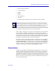
Introduction to SPMA for the SEHI100TX-22 Figure 1-2. The History Window Using the Mouse The UNIX mouse has three buttons, as shown in Figure 1-3. Procedures within the SPMA document set refer to these buttons as follows: Button 1 Button 2 Button 3 Figure 1-3. Mouse Buttons If youÕre using a two-button mouse, donÕt worry. SPMA doesnÕt make use of mouse button 2. Just click the left button for button 1 and the right mouse button when instructed to use mouse button 3.
Introduction to SPMA for the SEHI100TX-22 Whenever possible, we will instruct you on which mouse button to employ; however, menu buttons within SPMA applications will operate according to the convention employed by the active windowing system. By convention, menu buttons under the Motif windowing environment are activated by clicking the left mouse button (referred to as mouse button 1 in SPMA documentation), and there is no response to clicking the right button (mouse button 3).
Introduction to SPMA for the SEHI100TX-22 For additional information about Cabletron Systems products, visit our World Wide Web site: http://www.cabletron.com/. For technical support, select Service and Support. SEHI100TX Firmware SPMA support for the SEHI100TX has been tested against Þrmware version 1.00.06; if you have an earlier version of Þrmware and experience problems running SPMA, contact Cabletron Systems Global Support Center for upgrade information.
Introduction to SPMA for the SEHI100TX-22 1-8 SEHI100TX Firmware
Chapter 2 Using the SEHI100TX Hub View Navigating through the Hub View, monitoring hub performance; managing the hub The heart of SPECTRUM Portable Management Applications (SPMA) for the SEHI100TX is the Hub View, a graphical interface that gives you access to many of the functions that provide control over the device.
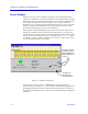
Using the SEHI100TX Hub View Navigating Through the Hub View Within the Hub View (Figure 2-1), you can click mouse buttons in different areas of the window to access various menus and initiate certain management tasks. The following sections describe the information displayed in the Hub View Front Panel and how to use the mouse in the Hub View Ports Display. Front Panel Device summary information Figure 2-1.
Using the SEHI100TX Hub View Uptime The time that the device has been running without interruption. The counter resets to 0 days 00:00:00 (HH:MM:SS) when one of the following occurs: ¥ Power to the device is cycled. ¥ The device is reset manually. Date and Time The date and time are taken from the deviceÕs internal clock. You can set the device date and time using the Device Status window; refer to page 2-10 for details. Device Name A text Þeld that you can use to help identify the device.
Using the SEHI100TX Hub View Clicking on the Device button displays the Device menu, Figure 2-2. Figure 2-2.
Using the SEHI100TX Hub View Note that the Device menu does not provide access to every application which is available to the SEHI100TX; some information is only available from the Module or Port menus, and several applications can only be accessed either from the icon menu (if you are running under a network management platform) or from the command line (if you are running in stand-alone mode).
Using the SEHI100TX Hub View Port Display Form Using the Module or Device menus, you can change the port display form shown in the Port Status boxes to any one of the following: - Load (% of theoretical maximum) - Traffic (Pkts/sec) - Collisions (Colls/sec) Module Type Displays the type of module, or device, whose ports are currently being displayed in the Ports Display.
Using the SEHI100TX Hub View Hub View Port Color Codes The Port Status boxes in the Hub View are color coded to indicate the portÕs connection status. The colors are consistent for all Port Display Forms except Admin Status; the exceptions are noted below. ¥ Green indicates that the port is active; that is, the port has been enabled by management, has a valid Link signal (if applicable), and is able to communicate with the station at the other end of the portÕs cable segment.
Using the SEHI100TX Hub View Figure 2-5. The SEHI100TXÕs Device, Module, and Port Menus Hub performance data available through these menus includes: ¥ Device, Module, and Port status descriptions. ¥ Device, Module, and Port statistics, which provide a complete breakdown of packet activity. ¥ Device, Module, and Port-level pie charts, graphs, and meters, for a graphical representation of the types and levels of trafÞc passing through the device.
Using the SEHI100TX Hub View Port display form options are: Load Shows a percentage for each active port that represents that portÕs portion of the theoretical maximum trafÞc level Ñ for Ethernet interfaces, 10 megabits per second; for Fast Ethernet interfaces, 100 megabits per second. Traffic Displays port trafÞc data in a packets/second format. Collisions Displays port trafÞc data in a collisions/second format.
Using the SEHI100TX Hub View Port Type Provides the following administrative information about the port: ¥ Admin/Link Status indicates the connection status of the port: - NOTE ON indicates that the port has a valid link signal or does not support a link signal. OFF indicates that the port has been turned off through management action. NLK (No Link) indicates that the port does not have a link to a device at the other end of the cable, or that there is no cable attached.
Using the SEHI100TX Hub View Figure 2-6. The Device Status Window Name and Location These text Þelds help identify this SEHI100TX-controlled HUBStack. The information you enter in the Name and Location boxes is written to the SEHI100TXÕs MIB and appears on the Hub View front panel. Contact Use the Contact box to record the name and phone number of the person responsible for the device. Note that the information entered here is not displayed on the Hub View front panel.
Using the SEHI100TX Hub View NOTE If your device Þrmware can accept four-digit year values, the Date Þeld will allow you to enter the year portion in one-, two-, or four-digit format. If you choose to enter one or two digits for the year, any value greater than or equal to 88 will be presumed to be in the 1900s; a value of 87 or less is presumed to be in the 2000s. No matter which entry format you choose, the year will still be displayed and set as a four-digit value.
Using the SEHI100TX Hub View Name This text Þeld can help identify the module, or device; the information entered here does not appear anywhere else in the Hub View. To edit the Module Name: 1. Highlight the text in the Name box and type in a new name. 2. Press Enter or Return on the keyboard to save your changes. Active Users This Þeld is not supported by the SEHI100TX-22. Module Type The type of module you are viewing.
Using the SEHI100TX Hub View Active Users This Þeld is not supported by the SEHI100TX-22. Checking Port Status You can open a Port Status window (Figure 2-9) for any port in the SEHI100TXcontrolled HUBStack. To open the Port Status window: 1. Click mouse button 3 in the Port Index or Port Status box to display the Port menu. 2. Drag down to Status and release. Figure 2-9.
Using the SEHI100TX Hub View NOTE ¥ Active Ñ The port has a valid connection with the device at the other end of the portÕs cable. ¥ Inactive Ñ The device at the other end of the cable is turned off, there is a break in the cable, or there is no device or cable connected. ¥ Not Supported Ñ The selected port does not support the Link feature, so the SEHI100TX cannot determine link status; this value will show only for thin coax (BNC), AUI, or transceiver ports.
Using the SEHI100TX Hub View ¥ ¥ ¥ Multi-Mode Fiber: SMA EPIM Multi-Mode Fiber: ST EPIM Single-Mode Fiber: ST EPIM Topology Type Indicates how the port is being used. The available types are: ¥ Station Ñ The port is receiving packets from no devices, a single device, or two devices. Note that a port in station status may actually be connected to multiple devices; station status simply indicates that no more than two devices are currently active.
Using the SEHI100TX Hub View To view device statistics at the Device, Module, or Port levels: 1. Display the Device, Module, or Port menu by clicking mouse button 3 in the appropriate area (refer to Figure 2-5, page 2-8). 2. Drag down to Statistics and then right to either General/Errors or Frames and release. The Hub View begins counting the selected statistics when you open the window; counts will be cumulative until you use the Reset button or close the window.
Using the SEHI100TX Hub View Multicast Packets The number of multicast packets received by this device, module, or port since the window was last opened or reset. Multicast packets are simultaneously addressed to more than one address, but fewer than all addresses. Collisions The number of collisions recorded by this device, module, or port since the window was last opened or reset.
Using the SEHI100TX Hub View 802.3 speciÞcations, or a node on the net is transmitting without Þrst listening for carrier sense (and beginning its illegal transmission more than 51.2 µs after the Þrst station began transmitting).
Using the SEHI100TX Hub View Knowing the priority scheme employed by the SEHI100TX can tell you a lot about the error counts you are seeing. For example, you know that the number of packets counted as CRC errors had only CRC errors Ñ they were of legal size (not runts or giants) and had no truncated bytes.
Using the SEHI100TX Hub View Figure 2-11. The Polling Intervals Window 3. To activate the desired polling, click mouse button 1 on the selection box to the right of each polling type field. 4. To change a polling interval, highlight the value you would like to change, and enter a new value in seconds. Note that the Use Defaults option must not be selected, or values will revert back to default levels when you click on Apply, and your changes will be ignored. 5.
Using the SEHI100TX Hub View Device Configuration This polling interval controls how often a survey is conducted of the devices installed in your SEHI100TX-controlled HUBStack. Port Operational State This polling interval controls the update of the information displayed in the Port Status boxes for each port in the device. Port state information includes link state (the color code) and admin state (on or off).
Chapter 3 Link/Seg Traps About Link and Segmentation traps; enabling and disabling these traps at the device, module, and port levels Among the traps which Cabletron devices are designed to generate are traps which indicate when a repeater port gains or loses a link signal, when the repeater segments (disconnects) a port due to collision activity, and when a segmented port becomes active again. In some networks, these Link and Segmentation traps may be more information than a network manager wants to see.
Link/Seg Traps NOTE Unterminated BNC (thin coax) ports appear in the Hub View as segmented ports. When you attach a thin coax cable or a 50 Ω terminator to a port, the repeater generates a portUnsegmenting trap; when you remove the cable or terminator, the repeater generates a portSegmenting trap. Note also that devices at both ends of the cable will generate the portUnsegmenting and portSegmenting traps, even if only one end of the cable has been disconnected.
Link/Seg Traps from the Hub View: 1. Click on to display the Device menu. 2. Drag down to Link/Seg Traps and release. from the command line (stand-alone mode): 1. From the appropriate directory, type spmarun r4hwtr NOTES The spmarun script invoked Þrst in the above command temporarily sets the environment variables SPMA needs to operate; be sure to use this command any time you launch an application from the command line.
Link/Seg Traps Configuring Link/Seg Traps for the Repeater To enable or disable Link and Segmentation traps for all ports on a repeater: 1. In the Repeater Link/Seg Traps window, click mouse button 1 on the repeater interface for which you would like to configure link and segmentation traps. 2. Click mouse button 1 on window, Figure 3-2, will appear. ; the Channel X Link/Seg Traps Figure 3-2. The Channel X Link/Seg Traps Window 3.
Link/Seg Traps Figure 3-3. The Module Traps Window 3. In the Module Traps window, click mouse button 1 to select the module for which you wish to configure link and segmentation traps. • If the Set Trap Status For field displays Selected Modules (the default setting), you can click to select any modules; to de-select any highlighted module, click on it again.
Link/Seg Traps Viewing and Configuring Link/Seg Traps for Ports To enable or disable Link and Segmentation traps for individual ports: 1. In the Repeater Link/Seg Traps window, select a repeater in the scroll list. 2. Click mouse button 1 on will appear. ; the Port Traps window, Figure 3-4, Figure 3-4. The Port Traps Window 3. In the Port Traps window, click mouse button 1 to select the port or ports for which you wish to configure traps.
Link/Seg Traps To change the setting in the Set Trap Status For field, click on the currently displayed setting, and drag down to select a new setting. 4. Click on the appropriate selection in the Link Traps field to Enable or Disable link traps for the selected ports, as desired. 5. Click on the appropriate selection in the Segmenting Traps field to Enable or Disable segmenting traps, as desired. 6. Click on window.
Link/Seg Traps 3-8 Enabling and Disabling Link/Seg Traps
Chapter 4 Repeater Redundancy Configuring and enabling redundant circuits; monitoring redundant circuits Setting Network Circuit Redundancy The redundancy application gives you the ability to deÞne redundant circuits for your SEHI100TX to ensure that critical network connections remain operational. Each circuit has a designated primary port and one or more backup ports.
Repeater Redundancy from the command line (stand-alone mode): 1. From the appropriate directory, type: spmarun r4red NOTES The spmarun script invoked Þrst in the above command temporarily sets the environment variables SPMA needs to operate; be sure to use this command any time you launch an application from the command line. The script is automatically invoked when you launch the application from the icon menu or from within the Hub View.
Repeater Redundancy Figure 4-2. The Channel X Redundancy Window 2. If you want to change a circuit’s name or the number of retries, highlight the appropriate circuit and click . The Change Circuit window, Figure 4-3, will appear. Figure 4-3.
Repeater Redundancy a. In the Name box, enter a new circuit name (up to 16 alphanumeric characters). b. In the Retries box, enter the number of retries — that is, the number of times the SEHI100TX tests the connection to the first IP address listed in the Circuit Addresses list box before it gives up and moves on to the next address. The valid range of retries you can enter into this field is 0-16. c. Be sure to click on changes. before exiting the window to save your 3.
Repeater Redundancy b. Specify up to 8 ports that will act as the redundant connections by using the Module and Port boxes to indicate each port, and then clicking on to enter each port into the circuit. c. By default, all ports are created as Inactive Backup ports. You should designate both a Primary port and an Active port. Typically, you would configure the same port to be both Primary and Active, but this is not required.
Repeater Redundancy To clear all redundancy conÞgurations, click on portion of the window. Reset does the following: ¥ ¥ ¥ ¥ NOTE in the All Circuits Deletes all entries in the Circuit Addresses box Changes the status of every Circuit to Disabled Reverts to previous Circuit Name(s) Clears all module and port entries After clearing redundancy settings by either method, backup ports remain disabled until you manually reenable them so that data loops do not occur.
Repeater Redundancy To set the Poll Interval: 1. In the All Circuits box, type in a new value in the Poll Interval field and click . Poll Interval is the time in seconds between retries (if the first attempt is unsuccessful). To set the Test Time: 1. In the All Circuits box, type a new test time in the Test Time field in a 24-hour HH:MM:SS format and click . The Test Time is the time of day when the SEHI100TX polls the addresses listed in each of the enabled circuits.
Repeater Redundancy 4-8 Monitoring Redundancy
Appendix A SEHI100TX MIB Structure SEHI100TX management information base configuration IETF MIB Support In addition to its proprietary features, the SEHI100TX currently supports the following IETF MIB: ¥ RFC 1213 MIB for Network Management of TCP/IP-based Internets: MIB-II SEHI100TX MIB Structure CabletronÕs newer intelligent devices Ñ like the SEHI100TX Ñ organize MIB data into a series of Òcomponents.Ó A MIB component is a logical grouping of MIB data, and each group controls a deÞned set of objects.
SEHI100TX MIB Structure information in the other components, even if those components have different community names; the Chassis MGR community names are the same as those assigned via Local Management. SEHI100TX LIM The SEHI100TX LIM, or Local Management, component contains the objects that provide out-of-band management via the Console port on the SEHI100TXÕs front panel. No objects from this component are used for remote management.
SEHI100TX MIB Structure NOTE The set of community names you assign via Local Management are those which apply to the SEHI100TX Chassis MGR MIB component. Newer versions of devices with this component-based MIB architecture have been simpliÞed somewhat; these devices support a single, global set of community names, with small modiÞcations added automatically to accommodate multiple instances of the same MIB component (such as network components).
SEHI100TX MIB Structure A-4 SEHI100TX MIB Structure
Index A E active port 4-5 Active Users 2-13, 2-14, 2-15 Add Circuit Address 4-4 Admin Status 2-10 Admin/Link Status 2-10 Alignment Errors 2-18 Avg Packet Size 2-17 enable ports 2-22 Error Priority Scheme 2-19 Errors 2-9 F Broadcast Packets 2-17 FCS value 2-18 Þrmware version 1-7, 2-5 Frame Sizes 2-9, 2-20 Front Panel 2-21 front panel 2-2 C G Change Name/Retries 4-3 Charts, Graphs, and Meters 1-3 Chassis MGR A-1 Circuit Name 4-4 Collisions 2-9, 2-18 color codes 2-2, 2-7 community name 2-1 community
Index Link/Seg Traps 2-4 Load 2-9 Local Management A-2 Location 2-3, 2-11 M MAC Address 2-3 Media Type 2-15 MIB component A-1 MIB component descriptions A-3 MIB I, II 1-3 MIBTree 1-3 misaligned packets 2-18 Module menu 2-7 Motif 1-4 Multicast Packets 2-18 Redundancy 2-4 redundant circuits 4-1 Repeater One A-2 Reset Circuit 4-5 Runt Frames 2-19 S O Save As Defaults 2-21 segmentation traps 3-1 segmented 2-7, 2-10, 2-15 SEHI100TX Þrmware 2-5 SEHI100TX MIB components A-1 Set Trap Status For 3-5, 3-6 Setti