
Manual


66
SmartStack STS16-20D/STS16-20R Token Ring Switches Installation and User Guide Installation
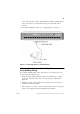
SmartStack STS-LM Connectors and LEDs
The following tables describe the connectors and LEDs on the STS-LM front
panel.
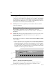
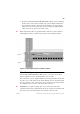
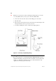
Connecting the Stacker Link Cable
When connecting two or more stacker link modules together to form a stack, you
must use the proprietary 50-pin cable supplied with the module.
The SmartStack STS16-20D/STS16-20R switch can be configured in three
different ways to form a stack of switches:
•
Two of the SmartStack STS16-20RM family switches back-to-back via two
SmartStack STS-LM modules
•
Up to five SmartStack STS16-20RM family Switches via one SmartStack
STS-5SU Stack Link Module and up to four SmartStack STS-LM Modules.
•
Up to eight SmartStack STS16-20RM family Switches via one SmartStack
STS-8SU Stacker Unit and up to eight SmartStack STS-LM Modules.
When inserting the cable connector, keep the connector straight to minimize the
risk of bent or damaged pins.
➽ Note:
Stacked SmartStack STS16-20RM family switches must all have the same
software version.
Connector Description
Stacker Port 50-pin SCSI-2 connector for proprietary
Stacker Link cable.
Table 10. SmartStack STS-LM Network Connector
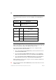
LED State Description
TX On Data is being transmitted from the
attached switch.
RX On Data is being received by the
attached switch.
ATTACH Off No connection has been established.
On A connection has been established.
Table 11. SmartStack STS-LM LEDs