SmartCell 6A000 User Guide 35 Industrial Way Rochester, NH 03866 USA (603) 332-9400 Part Number 04-0045-02 Rev-A Order Number 9032539
NOTICE Cabletron Systems reserves the right to make changes in specifications and other information contained in this document without prior notice. The reader should in all cases consult Cabletron Systems to determine whether any such changes have been made. The hardware, firmware, and software described in this manual are subject to change without notice.
FCC CLASS A NOTICE This device complies with Part 15 of the FCC rules. Operation is subject to the following two conditions: (1) this device may not cause harmful interference, and (2) this device must accept any interference received, including interference that may cause undesired operation. Note This equipment has been tested and found to comply with the limits for a Class A digital device, pursuant to Part 15 of the FCC rules.
DECLARATION OF CONFORMITY ADDENDUM Application of Council Directive(s): 89/336/EEC 73/23/EEC Manufacturer’s Name: Cabletron Systems, Inc. Manufacturer’s Address: 35 Industrial Way P. O. Box 5005 Rochester, NH 03866 Product Name: SmartCell 6A000 European Representative Name: Mr. J.
SAFETY INFORMATION CLASS 1 LASER TRANSCEIVERS The 6A-IOM-29-4, 6A-IOM-29-4-IR, 6A-IOM-29-4-LR, 6A-IOM-39-1 and 6A-IOM-39-1-LR connectors use Class 1 Laser transceivers. Read the following safety information before installing or operating the 6A-IOM-29-4. The Class 1 Laser transceivers use an optical feedback loop to maintain Class 1 operation limits. This control loop eliminates the need for maintenance checks or adjustments. The output is factory set, and does not allow any user adjustment.
FIBER OPTIC PROTECTIVE CAPS Caution READ BEFORE REMOVING FIBER OPTIC PROTECTIVE CAPS. Cable assemblies and MMF/SMF ports are shipped with protective caps to prevent contamination. To avoid contamination, replace port caps on all fiber optic devices when not in use. Cable assemblies and MMF/SMF ports that become contaminated may experience signal loss or difficulty inserting and removing cable assemblies from MMF/SMF ports.
REGULATORY COMPLIANCE SUMMARY SAFETY The SmartCell 6A000 meets the safety requirements of UL 1950, CSA C22.2 No. 950, EN 60950, IEC 950, and 73/23/EEC. EMC The SmartCell 6A000 meets the EMC requirements of FCC Part 15, EN 55022, CSA C108.8, VCCI V-3/93.01, EN 50082-1, and 89/336/EEC.
REVISION HISTORY Document Name: Document Part Number: Document Order number: SmartCell 6A000 User Guide 04-0045-02 Rev-A 9032539 Author: Bruce Jordan Editor: Carre Gibson Illustrator: Michael Fornalski Cover Designer: Michael Fornalski Date Revision Description September 1997 04-0045-01 Rev-A Initial Release March 1998 04-0045-02 Rev-A Second Release viii SmartCell 6A000 User Guide
TABLE OF CONTENTS 1 Introduction. . . . . . . . . . . . . . . . . . . . . . . . . . . . . . . . . . . . . . . . . . . . . . . . . . 1-1 2 Switch Installation and Setup . . . . . . . . . . . . . . . . . . . . . . . . . . . . . . . . . . . . 2-1 2.1 2.1.1 Unpacking the Switch . . . . . . . . . . . . . . . . . . . . . . . . . . . . . . . . . . . . . . . . . . . . . . . . . . . . . . . . . . . . . . 2-1 Check Accessory Carton Contents. . . . . . . . . . . . . . . . . . . . . . . . . . . . . . . . . . . .
TABLE OF CONTENTS 4.5 4.5.1 4.5.2 4.5.3 4.5.4 PVC Connections . . . . . . . . . . . . . . . . . . . . . . . . . . . . . . . . . . . . . . . . . . . . . . . . . . . . . . . . . . . . . . . . 4-11 Point-to-Point PVCs . . . . . . . . . . . . . . . . . . . . . . . . . . . . . . . . . . . . . . . . . . . . . . . . . . . . . . . . . . . 4-12 Point-to-Multipoint PVCs . . . . . . . . . . . . . . . . . . . . . . . . . . . . . . . . . . . . . . . . . . . . . . . . . . . . . .
TABLE OF CONTENTS C.3 Electronic Services . . . . . . . . . . . . . . . . . . . . . . . . . . . . . . . . . . . . . . . . . . . . . . . . . . . . . . . . . . . . . . . .C-1 C.4 Placing A Support Call . . . . . . . . . . . . . . . . . . . . . . . . . . . . . . . . . . . . . . . . . . . . . . . . . . . . . . . . . . . . .C-1 C.5 Hardware Warranty . . . . . . . . . . . . . . . . . . . . . . . . . . . . . . . . . . . . . . . . . . . . . . . . . . . . . . . . . . . . . . . .C-2 C.6 Software Warranty . .
TABLE OF CONTENTS xii SmartCell 6A000 User Guide
LIST OF FIGURES Figure 2-1 6A000-04 and 6A000-02 front panels. . . . . . . . . . . . . . . . . . . . . . . . . . . . . . . . . . . . . . . . . . . . . . . . . . 2-2 Figure 2-2 Installing the SmartCell 6A000. . . . . . . . . . . . . . . . . . . . . . . . . . . . . . . . . . . . . . . . . . . . . . . . . . . . . . . 2-5 Figure 2-3 6A000 console and network connections . . . . . . . . . . . . . . . . . . . . . . . . . . . . . . . . . . . . . . . . . . . . . . .
List of Figures xiv SmartCell 6A000 User Guide
LIST OF TABLES Table 2-1 I/O module ID numbers . . . . . . . . . . . . . . . . . . . . . . . . . . . . . . . . . . . . . . . . . . . . . . . . . . . . . . . . . . . . 2-2 Table 2-2 DS3 and E3 Module settings. . . . . . . . . . . . . . . . . . . . . . . . . . . . . . . . . . . . . . . . . . . . . . . . . . . . . . . . . 2-3 Table 2-3 SmartSwitch 6000 contents. . . . . . . . . . . . . . . . . . . . . . . . . . . . . . . . . . . . . . . . . . . . . . . . . . . . . . . . . .
List of Tables xvi SmartCell 6A000 User Guide
1 INTRODUCTION Welcome to the SmartCell 6A000 User Guide. The SmartCell 6A000 ATM switch is a module that fits into the SmartSwitch 6000 chassis. You can install as many as five SmartCell 6A000 switches into a SmartSwitch 6000 chassis (using the 6C305-3 power supply). The module is hot swappable, meaning that you can install and remove it without turning off or disconnecting the chassis. This manual will help you quickly and easily install and configure your SmartCell 6A000 switch.
Introduction 1-2 SmartCell 6A000 User Guide
2 SWITCH INSTALLATION AND SETUP After you read this chapter, you will be able to perform the following tasks: U U U U Install the SmartCell 6A000 switch module into the SmartSwitch 6000 chassis Complete the initial configuration Use the console interface Install the SmartSwitch ATM Administrator graphical management software 2.1 UNPACKING THE SWITCH Remove the accessory carton from the shipping box. Carefully remove the switch from its packing material. 2.1.
Inspecting the Switch Switch Installation and Setup ATM ATM FAIL STATUS POWER RX ENET TX ENET S Y S T E M 1 1 1 NO SYNC 2 2 2 A C 4 4 4 3 3 3 E T H E R N E T E T H E R N E T C O M 1 1 1 NO SYNC DATA NO SYNC DATA NO SYNC DATA 2 2 2 B 6A-IOM-21-4 6A-IOM-22-4 6A-IOM-21-4 D 6A-IOM-22-4 6A-IOM-21-4 6A-IOM-22-4 C C O M B DATA NO SYNC DATA NO SYNC DATA A FAIL STATUS POWER RX ENET TX ENET S Y S T E M D 3 3 3 4 4 4 Figure 2-1 6A000-04 and 6A000-02 front pa
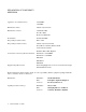
Switch Installation and Setup Table 2-1 Installing the Switch I/O module ID numbers (Continued) Face Plate Number Physical Specification 6A-IOM-29-4-LR 155 Mbps OC-3/STS-1, SMF-LR/SC (4 port) 6A-IOM-31-1 622 Mbps OC-12/STM-4, MMF/SC (1 port) 6A-IOM-39-1 622 Mbps OC-12/STM-4, SMF-IR/SC (1 port) 6A-IOM-39-1-LR 622 Mbps OC-12/STM-4, SMF-LR/SC (1 port) 6A-IOM-67-4 45 Mbps DS-3, Coax/BNC (4 port) 6A-IOM-77-4 34 Mbps E-3, Coax/BNC (4 port) If the hardware configuration is incorrect, contact Cabl
Installing the Switch 2p›F Switch Installation and Setup A single 6C205-1 power supply (the older version of the 6C205-3) can support only two SmartCell 6A000s within a SmartSwitch 6000 chassis. Three SmartCell 6A000s can reside within a SmartSwitch 6000 chassis that contains two 6C205-1 power supplies. Follow the instructions below to install the switch module into the chassis. Refer to Figure 2-2. s• Remove the metal blank that covers one of the empty slots in the chassis.
Switch Installation and Setup Configuring the Switch Rotate ejector to lock in place Circuit Card Metal Backpanel Card Guides Figure 2-2 Installing the SmartCell 6A000 2.4 CONFIGURING THE SWITCH Initial configuration of your SmartCell 6A000 switch consists of setting the name, Ethernet IP address, and subnet mask. Once these tasks are complete, the switch can be reached through your Ethernet network for additional configuration and administration.
Configuring the Switch Switch Installation and Setup ¢• Configure dumb terminals or PCs running emulation software with the following communication parameters: U U U U Baud rate = 9600 Data bits = 8 Stop bits = 1 Flow control = none •• Plug one end of the supplied RJ-45 UTP cable into the 9-pin RJ-45 adapter (see Figure 2-3) 2p›F For information about adapter wiring configurations, see Appendix A, "Specifications.
Switch Installation and Setup Configuring the Switch ATM FAIL STATUS POWER RX ENET TX ENET S Y S T E M 1 1 NO SYNC DATA NO SYNC DATA 2 2 6A-IOM-21-4 6A-IOM-22-4 3 3 4 Ethernet RJ-45 Port 4 Terminal RJ-45 Port 1 1 NO SYNC DATA NO SYNC DATA 2 2 6A-IOM-22-4 6A-IOM-21-4 3 3 4 4 Terminal Ethernet Hub Figure 2-3 6A000 console and network connections –• Start the dumb terminal or PC and its terminal emulation software.
Using the Console Switch Installation and Setup s¬• After you enter these parameters and reboot the switch, log off the local console connection. Perform additional configuration steps over your network using a telnet connection. 2p›F Only one console connection is allowed at any time. To reach the SmartCell 6A000 through telnet, you must exit the local terminal connection by entering the exit command. The following is an example of the initial configuration session: SmartCell ZX Version 2.
Switch Installation and Setup start: Using the Console Start a process on the switch; for example, start the LAN Emulation Configuration Server. restart: Restart a process on the switch; for example, restart a client. flush: Remove assigned values; for example, flush a route table. alias: Create easier names for often-used commands and their parameters. Entering parameters at the command line is optional. If a command requires parameter values, it prompts you for them.
Using the Console 2p›F 2.5.2 Switch Installation and Setup When you accept the (all) default for show, the information displayed is often abridged. Console Time-out The console can be configured to exit if it does not sense a key stroke within a defined length of time. By default, the SmartCell 6A000 is set to never time-out (value = 0).
Switch Installation and Setup 2.5.4 Using the Console Ambiguous Commands If you enter part of a command, and that part is not unique, the console displays a numbered list of possible matching commands. For example, entering show pnnin is ambiguous because there are several commands that start with “pnnin.
SmartSwitch ATM Administrator Switch Installation and Setup To obtain an explanation of a command and its parameters, enter the word help (or ?) before the command.
Switch Installation and Setup SmartSwitch ATM Administrator Figure 2-4 SmartSwitch ATM Administrator 2p›F Capabilities that are not available from the SmartSwitch ATM Administrator are debugging and tracing. SmartSwitch ATM Administrator can be installed on a PC running Windows NT 4.0, Windows NT 3.
SmartSwitch ATM Administrator Switch Installation and Setup s• If you are using diskettes, make backup copies of the SmartSwitch ATM Administrator diskettes. Put the original diskettes in a safe place; use them if your backup copies become unusable. Use your backup copies to complete the installation procedure. ¢• Load Disk 1 into drive a or note the network to the directory that contains the SmartSwitch ATM Administrator files. •• Start the installation software: † † NT 4.
Switch Installation and Setup SmartSwitch ATM Administrator ¢• Enter the default user name, admin. The user name is case sensitive. •• Enter the default password, admin, and click the OK button or press Enter. The password is case sensitive. T• The SmartSwitch ATM Administrator window appears. On the Applications menu, select User Management. 2.6.
SmartSwitch ATM Administrator 2-16 SmartCell 6A000 User Guide Switch Installation and Setup
3 IP OVER ATM AND LANE This chapter describes working with the SmartCell 6A000 IP over ATM VLAN and emulated LAN capabilities. At the end of this chapter you will be able to use your SmartCell 6A000 switch to • • Create an IP over ATM VLAN Create an emulated Ethernet LAN (LANE) 3.1 CREATING AN IP OVER ATM VLAN This section describes implementing IP over ATM on your SmartCell 6A000 switch. The following assumptions are made: • • • The 6A000 switch will have a client on the IP over ATM VLAN 1.
%•F"›amV˜"m˜,6˜p¦F•˜":1˜=/"2 3. ˜˜,6˜3¦F•˜":1˜"m=˜/"2' Enter the show client command to make sure the client is operational and to obtain the 20-byte ATM address of the ARP server. For instance, if you used the client number (client 1) from the example in step 2, enter the following command.
,6˜3¦F•˜":1˜"m=˜/"2' Note %•F"›amV˜"m˜'h¤d"›F=˜/"2˜˜ If configured devices fail to join the VLAN, see Chapter 4, Section 4.2.2, “UNI Routes.” Also, see Chapter 5, Section 5.1, “Troubleshooting IP Over ATM.” You have completed the process for creating an IP over ATM VLAN. Continue to the next section for instructions on creating an emulated LAN or go to Chapter 4, “Switch Administration,” for information about SmartCell 6A000 switch operations and maintenance. 3.1.
%•F"›amV˜"m˜'h¤d"›F=˜/"2 1. Enter the start ˜˜,6˜3¦F•˜":1˜"m=˜/"2' LECS command to activate LANE server services on this switch. SmartCell ZX # start lecs NOTICE - 'LECS' ***** LECS started ***** SmartCell ZX # 2. Create an ELAN on your SmartCell 6A000 switch by executing the following is an example. SmartCell ZX # add elan ELANNumber(0) : 1 ELANName(ELAN001): Marketing ConnectMethod(SVC): ELANType(802.3) Multipoint(YES) : MTU(1516) : Distribute(PROXY) : SmartCell ZX # 3. add elan command.
,6˜3¦F•˜":1˜"m=˜/"2' 4. Enter the show %•F"›amV˜"m˜'h¤d"›F=˜/"2˜˜ client command to make certain that the client is operational.
%•F"›amV˜"m˜'h¤d"›F=˜/"2 3.2.1 ˜˜,6˜3¦F•˜":1˜"m=˜/"2' ATM Addressing for LAN Emulation The SmartCell 6A000 provides a default format for ATM addresses used by LAN emulation. The default format is constructed as follows: netprefix + the MAC address of the device + a Selector Byte Where the netprefix is constructed from 39 + nine zero bytes + the last three bytes of the switch’s MAC address The Selector Byte specifies to whom the ATM address belongs.
,6˜3¦F•˜":1˜"m=˜/"2' %•F"›amV˜"m˜'h¤d"›F=˜/"2˜˜ This is analogous to a phone company that supports a communication system. Even though the phone company maintains the circuits, a call to the phone company itself cannot be made unless the phone company has its own number and connection on its own phone system. Similarly, VLAN membership (and the reachability) of a SmartCell 6A000 on any particular VLAN depends upon whether the SmartCell 6A000 has a local client connection for that VLAN.
%•F"›amV˜"m˜'h¤d"›F=˜/"2 3-8 SmartCell 6A000 User Guide ˜˜,6˜3¦F•˜":1˜"m=˜/"2'
4 SWITCH ADMINISTRATION This chapter contains software and hardware procedures that you might need to perform on your SmartCell 6A000 switch. These procedures include • • • • • • • • Backing up switch configuration Creating routes and connecting switches Using switch events and alarms Creating PVC connections Managing switch traffic Using low-level boot load switch commands Upgrading switch software Saving switch core dumps to a TFTP server 4.
ATM Routing Switch Administration The switch stores the IP address of the TFTP server, the path, and the backup file name. The next time you enter the or restore commands, these values are presented as the default IP address and path. For example, when you enter the restore command, the following display appears: backup SmartCell ZX# restore switch ServerIP(90.1.1.100) : Path(/back_dir/config-1) : SmartCell ZX # Backup file is valid.
Switch Administration 4. Enter the add ATM Routing ATMRoute command to create a static route to the IISP device: SmartCell ZX # add atmroute PortNumber(A1) : b2 AtmAddress() : 52:00:00:00:00:00:00:00:00:00:14:51:80 PrefixLength(104) : Index(0) : Type(Internal) :exterior Scope(0) : MetricsTag(0) : SmartCell ZX # Note 5. Enter the show The add ATMRoute command allows you to specify a set of metrics to be used with the route. For more on metrics and metric tags, see Section 4.2.3 “Route Metrics.
ATM Routing Switch Administration Note Dotted lines in the diagrams below represent one-way routes to the devices pointed to by the arrowheads. Each route is defined on the device from which the dotted line originates. A B LEC Physical link C IISP route IISP Domain PNNI Domain LECS Figure 4-1 IISP route across PNNI domain A second IISP device (Switch D) is added behind Switch A.
Switch Administration 4.2.2 ATM Routing UNI Routes Use the add ATMRoute command to create UNI routes. For example, connect an end station adapter (with MAC address 00:11:22:33:44:55) to port A2 of the SmartCell 6A000. If the adapter does not support ILMI or its ILMI is incompatible with the SmartCell 6A000, you must create a static UNI route between the adapter and port A2 of the SmartCell 6A000. 1.
ATM Routing 4.2.3 Switch Administration Route Metrics Route metrics are assigned to routes using a metric tag (one of the input parameters for add ATMRoute). The metric tag specifies a particular pair of incoming and outgoing metrics contained within a list of metrics. Metrics are created using the add PNNIMetric command. Each metric pair specifies a set of values that describe a route’s Service Category, cell rates, bandwidth, and administrative weight.
Switch Administration Enter show PNNIMetric IP Routing to view the newly created metric pair: SmartCell ZX # show pnnimetrics Metrics(ALL) : Metrics Metrics Tag Direction Index GCAC CLP Admin Wt Service Categories ================================================================================ 1 0x9 Incoming 0x10 CLP0+1 200 CBR 2 0x9 Outgoing 0x10 CLP0+1 200 CBR 3 0x111113 Outgoing 0x1 CLP0+1 5040 UBR 4 0x111113 Outgoing 0x2 CLP0+1 5040 ABR 5 0x111113 Outgoing 0x4 CLP0 5040 NRTVBR 6 0x111113 Outgoing
IP Routing Switch Administration Note SmartCell 6A000 IP routing performance is inadequate for routing between VLANs. If you need to create routes between VLANs on your SmartCell 6A000, use a router equipped with an ATM interface. Consult Cabletron Customer Support for recommended routers. For example, • • • • • • Switch SW1 and the NMS are on an Ethernet network with address 128.205.99.0. The IP address of SW1's Ethernet port is 128.205.99.254. The IP address of SW1's LANE client is 90.1.1.254.
Switch Administration Events and Alarms IP Route ELAN ATM Link SW2 Switch client on SW2, 90.1.1.33 Switch client on SW1 is defined as SW2’s gateway to the Ethernet NMS Switch client on SW1, 90.1.1.254 SW1 Ethernet interface 128.205.99.254 Ethernet network 128.205.99.0 Figure 4-3 IP routing through SW1 for connectivity to the Ethernet network 4.4 EVENTS AND ALARMS The SmartCell 6A000 switch records and reports its operation in real-time through the use of events and alarms.
Events and Alarms 4.4.2 Use the show Switch Administration Viewing Events and Alarms events command to view a list of the currently logged events.
Switch Administration Use the show alarms PVC Connections command to view a list of the currently logged alarms.
PVC Connections 4.5.1 Switch Administration Point-to-Point PVCs The procedure for setting up a PVC connection between two end nodes through the SmartCell 6A000 consists of specifying the ports and the virtual path and virtual channel identifiers (VPI and VCI). 1.
Switch Administration 1. PVC Connections Use add trafficdescriptor to create two new traffic descriptors, one for the forward direction, the other for the backward direction. For this example, for the forward traffic descriptor, we select UBR and accept the defaults.
PVC Connections 6. Switch Administration Configure the workstations for the same subnet and VPI/VCI pair = 0/101. The broadcasting workstation on port A1 can send traffic to the receiving workstations on ports B2, B3, and C1. 4.5.3 Connecting to Local Switch Client Through a PVC All PVC connections to the SmartCell 6A000 local clients use B4 (the CPU port) as the HighPort. Follow these instructions to connect an end node to a SmartCell 6A000 local client through a point-to-point PVC. 1.
Switch Administration PVC Connections Table 4-1 Values for VPI and VCI VCC Mask Index VPI Bits VPI Values VCI Bits VCI Values 0 0 0 12 0 to 4096 1 2 0 to 3 10 0 to 1023 2 4 0 to 15 8 0 to 255 3 6 0 to 63 6 0 to 63 Use the show vccmask command to view the four preconfigured VPI/VCI combinations.
PVC Connections 3. Switch Administration Use the set portconfig command to reconfigure a port to use the new values for VPI and VCI. For example, to set up a PVC on port A1 using the new VPI/VCI bit ranges (3/9), enter SmartCell ZX # set portconfig a1 PortAdminStatus(up) IlmiAdminStatus(enable) IlmiAddressRegistration(enable) IlmiConnectivity(enable) SigType(autoConfig) SigRole(other) InterfaceType(private) MaxVpiBits(0) MaxVciBits(12) MaxSvcVpi(7) MinSvcVci(32) MaxVccs(4096) SmartCell ZX # 4.
Switch Administration 4.6 Traffic Management TRAFFIC MANAGEMENT This section describes how the SmartCell 6A000 manages bandwidth and congestion. It briefly describes console commands that affect how the SmartCell 6A000 manages traffic. This section also provides guidelines for setting some traffic control parameters. Note For information on troubleshooting traffic congestion problems, see Chapter 5, “Troubleshooting.” The SmartCell 6A000 has extensive abilities for managing the flow of traffic.
Traffic Management Switch Administration Use the trafficdescriptor commands to view, create, and delete traffic descriptors. For example, enter the show trafficdescriptor command to view all currently defined traffic descriptors.
Switch Administration Traffic Management A user-defined PVC must have user-defined traffic descriptors. For instance, if a video link over a PVC requires a constant data flow of 5000 kb/s and a peak cell rate of 8000 kb/s, create a traffic descriptor for CBR traffic that specifies 5000 as the sustained cell rate and 8000 as the peak cell rate.
Traffic Management Use the command show referenced by VPI.
Switch Administration For example, enter the show Traffic Management porttrafficcongestion command to view current buffer utilization.
Traffic Management Switch Administration Quality of Service Queue Allocation Guidelines The following values are recommended settings for the Min and Max thresholds for the QoS queues under specific sustained traffic conditions. Use the settings in Table 4-3 as guidelines for threshold settings.
Switch Administration Upgrading and Changing Software Along with EFCI and backward RM cell marking, the SmartCell 6A000 uses standard RM cell marking. The switch discard threshold (show switchtrafficcongestion) corresponds to total shared buffer utilization and represents the point at which the switch considers itself congested and starts marking RM cells. Note The switch discard threshold is not user configurable and is shown only for information.
Upgrading and Changing Software 4.7.2 Switch Administration Boot Load Commands The following table describes the commands available from the boot load prompt, their use, and their associated parameters. Table 4-4 Boot load commands Command Action Parameters chpi Change default boot load image: chpi 0 = set boot load image 0 as default Sets one of two images of the boot load software as the default. Default boot load image is executed at start-up.
Switch Administration Upgrading and Changing Software Image is downloaded into boot PROM by df b chpi sets which is the default boot image initial boot routines boot image 0 POST is downloaded into flash RAM by df p ponf turns POST on and off.
Upgrading and Changing Software 5. Switch Administration Set up the TFTP/Bootp server tables (or equivalent file) with: - SmartCell 6A000 MAC address IP address of the SmartCell 6A000 Ethernet interface path to the image file on the TFTP/Bootp server 6. From the terminal connection, enter the reboot command. 7. When the following message appears, “Press any key to exit to boot load prompt.” stop the countdown by pressing any key. The boot load prompt (=>) appears on the terminal screen. 8.
Switch Administration Upgrading and Changing Software Changing the Default Boot Load Image Continuing with the example above, perform the following steps to set boot load image 0 back to being the default. 1. Reboot the SmartCell 6A000. 2. When the following message appears “Preparing to run Default Primary Image: 1 Enter 0 or 1 to override and force one of these primary image sectors to run:” press the zero (0) key. The SmartCell 6A000 loads boot load image 0. 3.
Upgrading and Changing Software Switch Administration ............................................................................ ............................................................................ ............................................................................ ....................................... Validity checks of POST software Downloaded file... All Validity checks OK Programming downloaded image into POST Software section, please wait...
Switch Administration Upgrading and Changing Software ........................................................................... ................................................... Validity checks of the Switch Software Downloaded file... All Validity checks OK Programming downloaded image into Switch Software section, please wait... New Switch Software programmed successfully => 9. Check whether the switch download is successful by entering the go command. 4.7.
Saving Core Dumps Switch Administration If the problem is corrected, enter the update firmware command to continue with the upgrade process. However, if you are unable to correct the problem, use the df (download flash) command and a TFTP/Bootp server to replace the operating software on your SmartCell 6A000. Follow the procedure outlined below: 1. Set up TFTP/Bootp server software on a workstation. 2. Connect both the TFTP/Bootp server and the SmartCell 6A000 to your Ethernet network.
Switch Administration Enter the set Saving Core Dumps CoreDump command to enable the core dump feature. For example, SmartCell ZX # set coredump EnableCoreDump(n) ServerIP() CoreDumpFile() userName() UserPassword() SmartCell ZX # : : : : y 204.95.77.240 /tftpboot/bobr/core bobr : < “y” to enable core dump feature < IP address of my TFTP server < full path name for core dump files < login name on the server < password Note The set CoreDump command uses FTP to create the core_cpu and core_cmn files.
Saving Core Dumps Switch Administration If a system failure occurs while the core dump feature is enabled, the SmartCell 6A000 console appears similar to the example below. The SmartCell 6A000 then begins sending images of its memory to the core dump files on the TFTP server. Illegal access. Bus Error.
5 TROUBLESHOOTING This chapter provides basic troubleshooting for diagnosing and fixing problems with VLAN, emulated LANs, and ATM traffic congestion. 5.1 TROUBLESHOOTING IP OVER ATM You have configured an IP over ATM VLAN, but your network applications are not working. Use these questions and tests to help determine the cause of the problem. 1. Check for connectivity: Try pinging between end nodes and from the SmartCell 6A000 (using start to its end nodes.
Troubleshooting LAN Emulation 5. Troubleshooting If working through these questions does not solve the problem, contact Cabletron Systems Customer Service. (See Appendix C, “Technical Support.”) 5.2 TROUBLESHOOTING LAN EMULATION You have configured an Emulated LAN and your network applications are not working. Use these questions and tests to help determine the cause of the problem. 1. Check for connectivity. Try pinging between end nodes.
Troubleshooting 6. Troubleshooting PNNI Links If working through these questions does not solve the problem, contact Cabletron Systems Customer Service. (See Appendix C, “Technical Support.”) 5.3 TROUBLESHOOTING PNNI LINKS You have physically connected another company’s ATM switch with your SmartCell 6A000. Each switch supports PNNI, but there is no connectivity between the two devices. Use the following procedure to diagnose and resolve the problem.
Troubleshooting Congestion 5.4.1 Troubleshooting Diagnosing Congestion 1. Enter the show 2. If cells are not being dropped on all ports, proceed to the “Port Congestion” section. 3. If cells are being dropped on all ports, the indication is global congestion. Proceed to the “Global Congestion” section. 5.4.2 portstats command, and take the default of (all). Global Congestion 1. Is the total cell drop rate equal to the Unknown VC cell drop rate? • • If yes, the switch is improperly set up.
Troubleshooting 5.4.3 Troubleshooting Congestion Port Congestion 1. Enter the show portstats command a few times, noting the value for cells dropped and unknown VCs dropped. Is the difference for cells dropped equal to the difference for VCs dropped? • • If yes, the switch is improperly set up. Check the switch configuration. 2. Enter the show cacinfo command for this port. Note the bandwidth allocated for each Quality of Service on this port. 3.
Troubleshooting Congestion 5-6 SmartCell 6A000 User Guide Troubleshooting
APPENDIX A SPECIFICATIONS This appendix describes SmartCell 6A000 switch hardware, product features, technical specifications, and adapter pin-out descriptions. "•s )832:˜6"2'/ This section describes the hardware components of the SmartCell 6A000 ATM switch. . Table A-1 Front panel LEDs LED Function FAIL (red) Normally OFF; ON indicates CPU failed. STATUS (amber) Normally OFF; ON indicates an error condition that prevents alarm information from being displayed to the console.
Technical Specifications Specifications FAIL STATUS Ejector Reset Button RX DATA TX DATA NO SYNC DATA DATA NO SYNC 2 2 3 3 4 4 E T H E R N E T Ethernet Port (10Base-T) 1 1 NO SYNC DATA NO SYNC DATA 2 2 6A-IOM-22-4 6A-IOM-21-4 D 3 3 4 4 Ejector Figure A-1 Front panel "•¢ :'%+2,%"/˜96'%,),%":,329 Table A-2 Hardware Specifications Specification Value Processor i960CF, 33 MHz Switching engine 2.
Specifications Technical Specifications Table A-2 Hardware Specifications (Continued) Specification Value Max I/O ports 7 for 6A000-02; 15 for 6A000-04 Switch latency 10 microseconds CPU DRAM memory 32 MB Buffer memory (cells) 32 K flash memory 8 MB Serial port RS-232c compliant; RJ-45 connector Ethernet port IEEE 802.3 compliant; RJ-45 connector Table A-3 Physical Specifications Specification Value Dimensions 41.9 cm x 6.1 cm x 28.6 cm 16.5" x 2.4" x 11.
Technical Specifications Table A-4 Specifications ATM Port Specifications (Continued) Max. Rx power Min. Rx power Range Media Port Speed Framing Connector Max. Tx Power Min. Tx power Cat. 5 UTP 155 Mbps STS-3 or STM-1 RJ-45 v -- -- -- 100 m 75 ohm coax 44.7 Mbps DS-3 nonchannelized BNC, female n/a n/a n/a n/a 150 m to DSX 75 ohm coax 44.7 Mbps DS-3 nonchannelized BNC, female n/a n/a n/a n/a 150 m to DSX 75 ohm coax 34.
Specifications Technical Specifications Table A-6 Management Standards and Specifications Management Protocol Supported MIBs SNMPv2c MIB II (RFC 1213) Interface Table MIB (RFC 1573) AToM MIB (RFC 1695) AToM2 MIB (pre-standard) LANE MIB (ATM Forum) ILMI 4.
Technical Specifications A-6 SmartCell 6A000 User Guide Specifications
APPENDIX B AGENT SUPPORT This appendix briefly describes the support provided for managing the SmartCell 6A000 using Simple Network Management Protocol (SNMP). B.1 MIB, SMI, MIB FILES AND INTERNET MIB HIERARCHY A MIB (Management Information Base) is the term used to represent a virtual store of management data on a device. Given the structure of management data, it can be operated upon (retrieved, created or modified) using the SNMP protocol.
MIB, SMI, MIB Files and Internet MIB Hierarchy Agent Support t root CCITT 0 ISO 1 joint ISO/CCITT 2 org 3 DOD 6 internet 1 directory 1 mgmt 2 experimental 3 private 4 MIB 1 Label from the root to this point is 1.3.6.1.2.1 Figure B-1 Internet MIB hierarchy B.1.1 ZeitNet Cabletron Proprietary MIBs The location of some of ZeitNet proprietary MIBs in the Internet hierarchy is shown in Figure B-2. All nodes starting with “zn” represent Zeitnet objects.
Agent Support MIB, SMI, MIB Files and Internet MIB Hierarchy . MIB 1 Label from the root to this point is 1.3.6.1 atomMIB 37 Private 4 enterprise 1 atmForum 353 znSwitchObjedcts 3333 ZeitNet 1295 znCommonMIB 199 znProducts 1 znCommonObjs 300 znManagedObjects 2 znTrapObjs 301 znAdminPolicyVal 202 znIpAtm 200 Figure B-2 ZeitNet Private MIBs In Figure B-2, the ZeitNet proprietary group is identified by 1.3.6.1.4.1.
MIB, SMI, MIB Files and Internet MIB Hierarchy Agent Support : Label from the root to this point is 1.3.6.1.4.1.1295 znManagedObjects 2 znIpATM (1295.2.200) znCommon (1295.2.300) znTrap (1295.2.301) znIisp (1295.2.3333) znLec (1295.2.3333.9.1.1) znLecDDCount (.1.1) Figure B-3 ZeitNet Cabletron 6A000 MIB object identifier example B.1.3 Supported protocols The SmartCell 6A000 supports Simple Network Management Protocol (SNMP). Both the SNMPv1 and SNMPv2c formats of the protocol are supported. B.1.
Agent Support MIB, SMI, MIB Files and Internet MIB Hierarchy Table B-1 Zeitnet proprietary MIB groupings (Continued) Name Object Identifier Function znIpAtmServer 1.3.6.1.4.1.1295.2.200.2 IP ATM Server Services znCommonObjs 1.3.6.1.4.1.1295.2.300 Zeitnet Specific Information znTrapObjs 1.3.6.1.4.1.1295.2.301 ZeitNet Traps znSwitchObjects 1.3.6.1.4.1.1295.2.3333 Switch/hardware specific information znSystem 1.3.6.1.4.1.1295.2.3333.
MIB, SMI, MIB Files and Internet MIB Hierarchy Note B.1.7 Agent Support Along with the MIBs, the diskette also contains a README file and the release note. MIB Exceptions With the current implementation of MIB files, conformance to ATM standards for the SmartCell 6A000 ATM switch includes the following exceptions.
Agent Support • • • • • • • • • • Managing the SmartCell 6A000 atmIfAdminAddrTable atmVclAddrBindTable atmAddrVclTable atmVplStatTable atmVplLogicalPortTable atmVclGenTable atmfMyOsiNmNsapAddress atmfVpcTable lecRouteDescrTable leRDArpTable B.2 MANAGING THE SMARTCELL 6A000 Your SmartCell 6A000 must be IP reachable by the NMS before it can be managed. The default connection between the SmartCell 6A000 and the NMS is the SmartCell 6A000 Ethernet interface.
Managing the SmartCell 6A000 Appendix B-8 SmartCell 6A000 User Guide Agent Support
APPENDIX C TECHNICAL SUPPORT This appendix tells you what to do if you need technical support for your SmartCell 6A000 switch. Cabletron offers several support and service programs that provide high-quality support to our customers. For technical support, first contact your place of purchase. If you need additional assistance, contact Cabletron Systems, Inc. There are several easy ways to reach Cabletron Customer Support and Service. C.
Hardware Warranty Technical Support • Detailed description of the issue (including history, what you've tried, and conditions under which you see this occur) • 6>À`Ý>ÀiÊ“œ`i•Ê˜Ö“LiÀ]ÊÃœvÍÝ>ÀiÊÜiÀÈœ˜]Ê>˜`ÊÃ݈ÍV…ÊVœ˜vˆ}ÖÀ>͈œ˜Ê-Í…>ÍʈÃ]ÊÝ…>ÍÊ«>ÀÍÊÍß«iÃÊ>Àiʈ˜ÊÝ…>ÍÊ Ã•œÍî C.5 HARDWARE WARRANTY Cabletron warrants its products against defects in the physical product for one year from the date of receipt by the end user (as shown by Proof of Purchase).
APPENDIX D ACRONYMS A AAL ATM Adaptation Layer AAL1 ATM Adaptation Layer Type 1 AAL2 ATM Adapter Layer Type 2 AAL3/4 ATM Adapter Layer Type 3/4 AAL5 ATM Adapter Layer Type 5 AALM ATM Adaptation Layer Mux ABR Available Bit Rate AFI Authority and Format Identifier ANSI American National Standards Institute API Application Programming Interface ARP Address Resolution Protocol ASCII American Standard Code for Information Interchange ATM Asynchronous Transfer Mode AVCR Available Cell
Acronyms BOOTP Boot Protocol BUS Broadcast and Unknown Server CAC Call Admission Control CAN Campus Area Network CAT-3 Category 3 unshielded twisted pair cable CAT-5 Category 5 unshielded twisted pair cable CBR Constant Bit Rate CCITT Comite Consultatif Internationale de Telegraphique et Telephonique (Consultative Committee on International Telegraphy and Telephony) CCR Current Cell Rate CDV Cell Delay Variation CER Cell Error Ratio CES Circuit Emulation Service CI Congestion Indic
Acronyms D DCC Digital Cross Connect, generic DACS or Direct Connect Card, data interface module DF Download Flash DS-0 Digital Signaling 0 DS-1 Digital Signaling 1 DS-3 Digital Signaling 3 DTE Data Terminal Equipment DTL Designated Transit List DVT Delay Variation Tolerance E-1 European standard for digital transmission service at 2 Mb/s. E-3 European standard for digital transmission service at 34.
Acronyms F FCS Frame Check Sequence FIFO First In First Out FTP File Transfer Protocol GB/S Gigabits per second GCAC Generic Call Admission Control GCRA Generic Cell Rate Algorithm GFC Generic Flow Control HEC Header Error Check IEEE Institute of Electrical and Electronic Engineers ICMP Internet Control Message Protocol ID Identification Number IE Information Element IETF Internet Engineering Task Force IISP Interim Inter-Switch Signaling Protocol G H I Appendix D-4 SmartCell
Acronyms ILMI Integrated Local Management Interface I/O Input/Output IOM Input/Output Module IP Internet Protocol IP/ATM Internet Protocol over ATM IPX Internetwork Packet Exchange protocol ITU-TSS International Telecommunications Union-Telecommunications Standards Sector ISDN Integrated Service Digital Network JPEG Joint Photographic Experts Group KB/S Kilobits per second LAN Local Area Network LANE LAN Emulation LE LAN Emulation LE-ARP LAN Emulation-Address Resolution Protocol
Acronyms LECSELA LAN Emulation Configuration Server Emulated LAN N LES LANE Server LESELAN LANE Server Emulated LAN LIS Logical IP Subnetwork LLC Logical Link Control LMI Local Management Interface MAC Media Access Control MAN Metropolitan Area Network MB/S Megabits per second MBS Maximum Burst Size MCR Minimum Cell Rate MIB Management Information Base MMF Multi-Mode Fiber MP Multi-Point MSM Main Switch Module MTU Maximum Transfer Unit NAKS Negative Acknowledges NDIS Network
Acronyms NETBEUI NetBIOS Extension User Interface NFS Network File System NIC Network Interface Controller/Card NLS Natural Language Syntax NMS Network Management System NNI Network Node Interface or Network-to-Network Interface NRT-VBR Non Real Time - Variable Bit Rate NRZ Non-Return to Zero NSAP Network Services Access Point OAM Operations and Maintenance OAM&P Operations, Administration, Maintenance and Provisioning OC-1 Optical Carrier 1 OC-N Optical Carrier n (where "n" is an inte
Acronyms PDU Protocol Data Unit PGL Peer Group Leader PMD Physical Media Dependent Sub-layer PMP Point-to-Multipoint P-NNI Private Network Node Interface or Private Network-to-Network Interface PPD Partial Packet Discard PROM Programmable Read-Only Memory PTI Payload Type Indicator PTP Point-to-Point PTSE PNNI Topology State Element PTSE PNNI Topology State Packet PVC Permanent or Provisioned Virtual Circuit QOS Quality of Service QSAAL Q-Signaling ATM Adaptation Layer.
Acronyms RM Resource Management RMA Return Merchandise Authorization RQU Receive Queue Underrun RS-# Recommended Standard defined by Electronic Industries Association RT-VBR Real Time - Variable Bit Rate RW Read-Write Access SAAL Signaling ATM Adaptation Layer SAR Segmentation And Reassembly S SAR-PDU SAR Protocol Data Unit SBE System Bus Error SCR Sustainable Cell Rate SDH Synchronous Digital Hierarchy SEAL Simple Efficient Adaptation Layer SMF Single Mode Fiber SMDS Switched M
Acronyms SVC Switched Virtual Circuit SVCC Switched Virtual Channel Connection T-1 Transmission System 1 T-3 Transmission System 3 TAXI Transparent Asynchronous Transmitter/Receiver Interface TCP Transmission Control Protocol TD Traffic Descriptor TDM Time-Division Multiplexing TFTP Trivial File Transfer Protocol TLV Type, Length and Value UBR Unspecified Bit Rate UME UNI Management Entity UNI User-Network Interface UP Unnumbered Poll UPC Usage Parameter Control UTOPIA Univer
Acronyms V VBR/RT Variable Bit Rate/Real Time VBR/NRT Variable Bit Rate/Non-real Time VC Virtual Circuit VCC Virtual Channel Connection VCI Virtual Channel Identifier VCL Virtual Channel Link VLAN Virtual LAN VP Virtual Path VPC Virtual Path Connection VPI Virtual Path Identifier VPN Virtual Private Network VT Virtual Tributary WAN Wide Area Network W SmartCell 6A000 User Guide Appendix D-11
Acronyms Appendix D-12 SmartCell 6A000 User Guide
INDEX Numerics B 6A000-02.................................................. 2-1 6A000-04.................................................. 2-1 6A-IOM-21-4 ........................................... 2-2 6A-IOM-22-4 ........................................... 2-2 6A-IOM-29-4 ........................................... 2-2 6A-IOM-29-4-IR...................................... 2-2 6A-IOM-29-4-LR..................................... 2-3 6A-IOM-31-1 ........................................... 2-3 6A-IOM-39-1 ..
Index RM cells........................................... 4-22 troubleshooting .................................. 5-3 console commands ................................... 2-8 add...................................................... 2-8 affecting the agent............................. B-7 alias .................................................... 2-9 create.................................................. 2-8 delete.................................................. 2-8 display.............................
Index G go............................................................ 4-24 MAC address ..................................... 3-3 server type.......................................... 3-1 troubleshooting .................................. 5-1 IP routing.................................................. 4-7 H hardware specifications........................... A-2 hardware warranty................................... C-2 he ............................................................ 4-24 help..............
Index P parallel routes ........................................... 4-7 partial commands ................................... 2-11 PC serial port adapter pin-out.................. A-5 peak cell rate........................................... 4-17 physical specifications............................. A-3 placing a support call............................... C-1 plcp ........................................................... 2-3 PNNI.........................................................
Index specifications ATM ports ........................................ A-3 front panel......................................... A-1 management standards...................... A-5 physical............................................. A-3 protocols standards ........................... A-4 start....................................................2-8, 2-9 starting the switch .................................... 2-8 supported MIBs....................................... A-5 sustainable cell rate ..............
Index viewing route metrics ............................... 4-7 VPI non-zero values................................ 4-14 VPI bits................................................... 4-14 VPI/VCI pairs......................................... 4-14 Z ZeitNet Cabletron proprietary MIBs .......