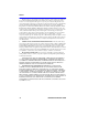
SSR-600 Installation Guide Title Page RESET PWR LNK CPU STS 9033032-01 CONSOLE ETHERNET 1 ETHERNET 2 10/100 10/100 SPD/100 SPD/100 XMT RCV XMT RCV WIDE AREA 1 WIDE AREA 2 TELCO TELCO
NOTICE Cabletron Systems reserves the right to make changes in specifications and other information contained in this document without prior notice. The reader should in all cases consult Cabletron Systems to determine whether any such changes have been made. The hardware, firmware, or software described in this manual is subject to change without notice.
Notice INDUSTRY CANADA NOTICE This digital apparatus does not exceed the Class A limits for radio noise emissions from digital apparatus set out in the Radio Interference Regulations of the Canadian Department of Communications. Le présent appareil numérique n’émet pas de bruits radioélectriques dépassant les limites applicables aux appareils numériques de la class A prescrites dans le Règlement sur le brouillage radioélectrique édicté par le ministère des Communications du Canada.
Notice CABLETRON SYSTEMS, INC. PROGRAM LICENSE AGREEMENT IMPORTANT: THIS LICENSE APPLIES FOR USE OF PRODUCT IN THE FOLLOWING GEOGRAPHICAL REGIONS: CANADA MEXICO CENTRAL AMERICA SOUTH AMERICA BEFORE OPENING OR UTILIZING THE ENCLOSED PRODUCT, CAREFULLY READ THIS LICENSE AGREEMENT. This document is an agreement (“Agreement”) between You, the end user, and Cabletron Systems, Inc.
Notice If the Program is exported from the United States pursuant to the License Exception TSR under the U.S.
Notice CABLETRON SYSTEMS SALES AND SERVICE, INC. PROGRAM LICENSE AGREEMENT IMPORTANT: THIS LICENSE APPLIES FOR USE OF PRODUCT IN THE UNITED STATES OF AMERICA AND BY UNITED STATES OF AMERICA GOVERNMENT END USERS. BEFORE OPENING OR UTILIZING THE ENCLOSED PRODUCT, CAREFULLY READ THIS LICENSE AGREEMENT. This document is an agreement (“Agreement”) between You, the end user, and Cabletron Systems Sales and Service, Inc.
Notice If the Program is exported from the United States pursuant to the License Exception TSR under the U.S.
Notice CABLETRON SYSTEMS LIMITED PROGRAM LICENSE AGREEMENT IMPORTANT: THIS LICENSE APPLIES FOR THE USE OF THE PRODUCT IN THE FOLLOWING GEOGRAPHICAL REGIONS: EUROPE MIDDLE EAST AFRICA ASIA AUSTRALIA PACIFIC RIM BEFORE OPENING OR UTILIZING THE ENCLOSED PRODUCT, CAREFULLY READ THIS LICENSE AGREEMENT.
Notice If the Program is exported from the United States pursuant to the License Exception TSR under the U.S.
Notice DECLARATION OF CONFORMITY Application of Council Directive(s): Manufacturer’s Name: Manufacturer’s Address: European Representative Name: European Representative Address: Conformance to Directive(s)/Product Standards: Equipment Type/Environment: 89/336/EEC 73/23/EEC Cabletron Systems, Inc. 35 Industrial Way PO Box 5005 Rochester, NH 03867 Mr. J.
Notice x SSR-600 Installation Guide
CONTENTS Figures ................................................................................................... xiii Tables..................................................................................................... xiv INTRODUCTION Using This Guide ...........................................................................xv Structure of This Guide..................................................................xv SSR-600 Features..............................................................
Contents 3.4 3.5 3.6 3.7 Installing the SSR-600 .................................................................3-6 3.4.1 Tabletop and Shelf Installations ......................................3-6 3.4.2 SSR-600 Rackmount Installation ....................................3-6 3.4.2.1 Tools Required................................................3-7 3.4.2.2 Materials Required..........................................3-7 3.4.2.3 Attaching the Rackmount Brackets.................
FIGURES 1-1 3-1 3-2 3-3 3-4 3-5 3-6 3-7 3-8 3-9 3-10 3-11 3-12 4-1 4-2 SSR-600................................................................................... 1-1 Removing the Chassis Cover................................................... 3-3 Option Placement..................................................................... 3-4 WAN SWPIM Ports .................................................................. 3-5 Removing an Existing SWPIM .................................................
TABLES 4-1 4-3 4-2 4-4 1-1 1-2 SSR-600 Hardware LED States ............................................... 4-2 SSR-600 LAN LED States........................................................ 4-3 Console Port LEDs................................................................... 4-3 Four Position Switch Bank Functions ...................................... 4-4 Console Port Connector Pinout................................................A-2 Fast Ethernet RJ45 Pinout ..........................................
INTRODUCTION Only qualified personnel should perform installation procedures. Welcome to the Cabletron Systems SSR-600 Installation Guide. SSR stands for SmartSwitch Router. This guide provides installation, basic configuration information, hardware specifications and troubleshooting tips for the SSR-600. NOTE Since most of the information in this manual applies to either model regardless of the power supply, the generic term SSR-600 will be used.
Introduction Chapter 3, Installation, provides detailed instructions for connecting the SSR-600 to a network. Chapter 4, Troubleshooting, Switches, and LED Indications, provides detailed troubleshooting tips using the LANVIEW LEDs on the SSR-600, along with hardware information. Appendix A, Specifications, contains information on functionality and operating specifications, regulatory compliance, connector pinouts, environmental requirements, and physical properties.
Introduction RELATED MANUALS The following manuals may help the user to set up and manage the SSR-600: Cabletron Systems Ethernet Technology Guide Cabletron Systems Cabling Guide The manuals referenced above can be obtained on the World Wide Web in Adobe Acrobat Portable Document Format (PDF) at the following site: http://www.cabletron.
Introduction DOCUMENT CONVENTIONS The following conventions may be used in this document: NOTE TIP ! Note symbol. Calls the reader’s attention to any item of information that may be of special importance. Tip symbol. Conveys helpful hints concerning procedures or actions. Caution symbol. Contains information essential to avoid damage to the equipment. CAUTION Electrical Hazard Warning symbol. Warns against an action that could result in personal injury or death due to an electrical hazard.
Introduction GETTING HELP For additional support related to this device or document, contact Cabletron Systems using one of the following methods: World Wide Web http://www.cabletron.com/ Phone (603) 332-9400 Internet mail support@cabletron.com FTP ftp://ftp.cabletron.com/ anonymous your email address Login Password To send comments or suggestions concerning this document, contact the Cabletron Systems Technical Writing Department via the following email address: TechWriting@cabletron.
Introduction xx SSR-600 Installation Guide
CHAPTER 1 OVERVIEW OF THE SSR-600 The SSR-600 (Figure 1-1) is a device that provides Ethernet Local Area Network (LAN) connectivity via two fixed Ethernet ports, and offers high-speed Wide Area Network (WAN) access to remote sites via two optional Sliding WAN Physical Interface Modules (SWPIMs). The SSR-600 operates from a standard ac power source.
Chapter 1: Overview of the SSR-600 • The SWPIM-DDS provides a 56 Kbps or 64 Kbps Digital Data Service (DDS) connection. The SWPIM-DDS supports remote CSU diagnostic or 64 Kbps clear channel loopback and non-latching remote DSU diagnostic loopback. • The SWPIM-E1 provides an E1 interface through a front panel RJ45 port and includes a built-in CSU/DSU for direct connection to an E1 line. The SWPIM-E1 provides both Full E1 or Fractional E1 using 56 or 64 Kbps Time Slots with a total throughput of up to 2.
Remote Management 1.1.4 LANVIEW LEDs Cabletron Systems LANVIEW Status Monitoring and Diagnostics System is a troubleshooting tool that helps in diagnosing power failures, collisions, cable faults, and link problems. The LANVIEW LEDs are located on the SSR-600 front panel. 1.1.5 RESET Button The front panel RESET button reboots the SSR-600 and initializes the processor. The RESET button is also used with the mode switches to clear NVRAM. 1.1.
Chapter 1: Overview of the SSR-600 1.3 OPTIONAL FEATURES Rack Mounting Capabilities - The SSR-600 can be installed in a 19-inch rack with the optional mounting brackets and screws (Cabletron part number SSR-600-RCK-KIT). Refer to Chapter 3 for complete rack mounting instructions.
CHAPTER 2 NETWORK REQUIREMENTS Before installing the SSR-600, review the requirements and specifications referred to in this chapter concerning the following: • 10BASE-T Twisted Pair Network (Section 2.1) • 100BASE-TX Twisted Pair Network (Section 2.2) The network installation must meet the guidelines in this chapter and in the documents referenced in this chapter to ensure satisfactory performance of the equipment. Failure to follow the guidelines may produce poor network performance.
Chapter 2: Network Requirements 2.2 100BASE-TX NETWORK The two fixed front panel ports of the SSR-600 provide an RJ45 connection that supports Category 5 UTP cabling. The device at the other end of the twisted pair segment must meet IEEE 802.3u 100BASE-TX Fast Ethernet network requirements for the devices to operate at 100 Mbps. Refer to the Cabletron Systems Cabling Guide for details.
CHAPTER 3 INSTALLATION This chapter outlines the procedure for setting up the SSR-600 and attaching it to the network. Ensure that the network meets the guidelines and requirements outlined in Chapter 2 before installing the SSR-600. Sections of this installation procedure may require the following items: • Antistatic wrist strap (provided with the SSR-600) • Phillips screwdriver 3.1 GUIDELINES FOR INSTALLATION Only qualified personnel should perform installation procedures.
Chapter 3: Installation 3.2 UNPACKING THE SSR-600 Unpack the SSR-600 as follows: 1. Remove the shipping material from the box and carefully remove the SSR-600. 2. Visually inspect the SSR-600. If there are any signs of damage, contact Cabletron Systems (refer to the Getting Help section) immediately. 3. Read any SSR-600 Release Notes included in the shipping box for any important up-to-date information before proceeding. 3.
Installing Options To remove the chassis cover, proceed as follows: 1. Disconnect the SSR-600 from the network as follows (if applicable): a. Unplug the power cord(s) from the rear of the SSR-600 chassis. TIP Before performing step b, mark any cables connected to the SSR-600 according to their associated port numbers. This is recommended for ease of reinstallation. b. Disconnect any network cables attached to the SSR-600. 2.
Chapter 3: Installation 3.3.2 ! CAUTION Optional SSR-600-ECM Installation Failure to follow the procedures in the indicated documentation can result in damage to either the installed option or the SSR-600. Figure 3-2 details the board layout of the SSR-600 to show where the SSR-600-ECM can be installed. To install an SSR-600-ECM to enhance the performance of your SSR-600, refer to the instructions enclosed with the SSR-600-ECM.
Installing Options 3.3.3 Installing Sliding WAN Physical Interface Modules The SSR-600 is capable of having up to two Sliding WAN Physical Interface Modules (SWPIMs) installed into its chassis. Figure 3-3 indicates the ports in the SSR-600 into which the SWPIMs can be installed. Failure to follow the procedures for installation in the indicated documentation can result in damage to either the installed option or the SSR-600.
Chapter 3: Installation 3.4 INSTALLING THE SSR-600 The SSR-600 may be installed on a tabletop, shelf or in a 19-inch rack. Refer to Section 3.4.1 for information concerning a tabletop or shelf installation. Section 3.4.2 describes the rackmount installation. 3.4.1 ! CAUTION Tabletop and Shelf Installations Before performing installation procedures, ensure that the requirements outlined in Section 3.1, Guidelines for Installation, are met.
Installing the SSR-600 Rackmounting the SSR-600 requires the following steps: • Attaching the rackmount brackets to the SSR-600 • Installing the SSR-600 in a 19-inch rack 3.4.2.1 Tools Required • Phillips screwdriver • Flat blade screwdriver 3.4.2.2 Materials Required 1.
Chapter 3: Installation 3.4.2.3 Attaching the Rackmount Brackets Proceed as follows to attach the rackmount brackets: 1. Locate the two rackmount brackets. 2. With the faceplate, or front of the SSR-600, towards you, align the front of the bracket with the front of the SSR-600. Locate the slots that align with the rear flanges of the bracket. See Figure 3-7. 3. Swing the front of the bracket out and insert the flanges into the slots.
Installing the SSR-600 5. Repeat steps 1 through 4 for the other side. 6. The SSR-600 may be mounted with the back of the unit facing out of the rack. In this position, the screws will be attached along the bottom edge of the SSR-600 (the SSR-600 must be right-side up). Otherwise, all other instructions apply, substituting the back of the SSR-600 for the front in the instructions. 7. Position the SSR-600 between the vertical frame members of the 19-inch rack, as shown in Figure 3-9.
Chapter 3: Installation 3.5 NOTE CONNECTING TO THE POWER SOURCE The SSR-600 has universal power supplies. This allows you to connect the SSR-600 to power sources of 100–125 or 200–240 Vac, at 50 or 60 Hz. The voltage is automatically sensed when the power cord is plugged in. To connect the SSR-600 to the power source, perform the following steps: 1. Plug the power cord into the back panel of the SSR-600. 2. Plug the other end of the power cord into a grounded wall outlet.
Connecting to the Network 3.6 CONNECTING TO THE NETWORK This section provides the procedures for connecting the Ethernet ports of the SSR-600 to the network, and directions for information on connecting the WAN ports. For more information, refer to Chapter 2. 3.6.1 Connecting to the Fast Ethernet Ports The two fixed front panel ports of the SSR-600 are 10/100 Fast Ethernet ports with internal crossovers. When connecting a workstation to the SSR-600, use a straight-through cable.
Chapter 3: Installation 3. Verify that a link exists by checking that the port RCV (Receive) LED is ON (flashing amber, blinking green, or solid green). If the RCV LED is OFF and the XMT (Transmit) LED is not blinking amber, perform the following steps: a. Verify that the cabling being used is Category 5 UTP with an impedance between 85 and 111 ohms. If the port is to operate at 100 Mbps, category 5 cabling must be used. b.
Software Configuration TO SSR600 Ethernet Port NOTE: RX+/RX- and TX+/TXmust share a common color pair. TO Other Device Port RX+ 1 1 RX+ RX- 2 2 RX- TX+ 3 3 TX+ TX- 6 6 TX- RJ45 to RJ45 Figure 3-12 Straight-Through Cable RJ45 Pinouts d. Ensure that the twisted pair connection meets the dB loss and cable specifications outlined in the Cabletron Systems Cabling Guide. Refer to the Introduction for information on obtaining this document.
Chapter 3: Installation 3-14 SSR-600 Installation Guide
CHAPTER 4 TROUBLESHOOTING, SWITCHES, AND LED INDICATIONS This chapter is used to aid in determining hardware indications of operation and problems, and switch settings. Figure 4-1 shows the front panel LEDs for the SSR-600. Table 4-1, Table 4-2, and Table 4-3 describe LED states. Table 4-4 describes switch positions. If you are having difficulty installing and configuring the SSR-600, perform the following steps: • Review Chapter 3 (Installation). • Verify that power has been applied to the SSR-600.
Chapter 4: Troubleshooting, Switches, and LED Indications 4.1 FRONT PANEL LED INDICATIONS Table 4-1 LED SSR-600 Hardware LED States Color OFF None of the installed power supplies are operating, and the battery backup board is not operating (or not installed). SOLID GREEN All installed power supplies are operational. SOLID YELLOW One power supply is operational, and the other is not operating (this indication only applies when 2 power supplies are installed).
Front Panel LED Indications Table 4-2 LED Console Port LEDs Color OFF Link (LNK) Status (STS) No modem or no data. SOLID GREEN Modem attached, ready. FLASHING YELLOW Modem attached, passing data. SOLID RED Modem attached, not ready. OFF Port idle, no connection. BLINKING GREEN Modem attached, carrier not detected. SOLID GREEN Modem attached, carrier detected. BLINKING YELLOW Port in test mode. SOLID YELLOW Console attached.
Chapter 4: Troubleshooting, Switches, and LED Indications 4.2 SWITCHES The SSR-600 has two switches on the main motherboard, a thermal switch and a switch bank. Thermal Switch The thermal switch will close if the temperature inside the device exceeds 65°C when the SSR-600 is operating. The thermal switch then notifies the processor that the temperature in the SSR-600 exceeded 65°C. This information can be used to send a trap and/or log a message.
Switches 4.2.1 Switch Function Procedure These steps must be followed to use the switch function: 1. Remove power to the SSR-600. 2. Remove the cover of the SSR-600. Refer to Section 3.3.1. 3. Refer to Table 4-4 for a description of the switch functions. 4. Locate the switch bank in Figure 4-2. For the function you need, flip the appropriate switch from one side to the other side. The initial state of the switch does not matter. 5. Replace the cover. 6. Restore power to the SSR-600.
Chapter 4: Troubleshooting, Switches, and LED Indications 4.3 TROUBLESHOOTING SSR-600 HARDWARE Power (PWR) LED is OFF • Check the power source. • Check that the power connections are firmly plugged in to the back panel of the SSR-600. Processor (CPU) LED is OFF The CPU stays OFF for an extended amount of time, and the power (PWR) light remains on. The CPU is in an unknown state. • Contact Cabletron Systems (refer to Getting Help in the Introduction).
APPENDIX A SPECIFICATIONS This section describes the environmental specifications and safety and approval requirements for the SSR-600. Cabletron Systems reserves the right to change these specifications at any time without notice. A.1 PHYSICAL PROPERTIES Dimensions: 4.45 H x 43.18 W x 39.37 D (cm) 1.75 H x 17.0 W x 15.5 D (in) Weight (Unit): 6.3 kg (13.
Appendix A: Specifications A.1.1 Console Port The RJ45 labled “console” on the front panel of the SSR-600 is used to access the Command Line Interface (CLI). Refer to the appropriate software manual for details. See Related Manuals in the Introduction. Table 1-1 A.1.
Environmental Requirements A.2 ENVIRONMENTAL REQUIREMENTS Operating Temperature: +5° to +40°C (41° to 104°F) Non-operating Temperature: -30° to +90°C (-22° to 194°F) Operating Humidity: 5% to 90% (non-condensing) A.3 REGULATORY COMPLIANCE Safety UL 1950 (without D3 deviations), CSA C22.2 No.
Appendix A: Specifications A-4 SSR-600 Installation Guide
INDEX Numerics 100BASE-TX requirements 2-2 10BASE-T connection 3-11 requirements 2-1 C Cable specifications 100BASE-TX network 2-2 10BASE-T network 2-1 Connecting to the network 3-11 Console Port 1-3, A-2 Cover Removing 3-2 D Daughter Board 1-4 Document Conventions xviii SSR-600-ECM 3-4 SWPIMs 3-5 L LAN support 1-2 LANVIEW LEDs 1-3 LED Indication Tables 4-2 O Optional Features 1-4 Optional modules placement in the SSR600 3-4 P Physical Properties A-1 Power Connecting the SSR600 3-10 R E Flash EEPROM
Index U Unpacking the SSR600 3-2 W WAN Connection 1-1 WAN Network Requirements 2-2 Index-2 SSR-600 Installation Guide