
Installation guide

Chapter 3: Installation
3-12 SSR-600 Installation Guide
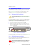
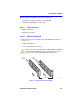
3. Verify that a link exists by checking that the port RCV (Receive) LED
is ON (flashing amber, blinking green, or solid green). If the RCV
LED is OFF and the XMT (Transmit) LED is not blinking amber,
perform the following steps:
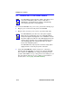
a. Verify that the cabling being used is Category 5 UTP with an
impedance between 85 and 111 ohms. If the port is to operate at
100 Mbps, category 5 cabling must be used.
b. Verify that the device at the other end of the twisted pair segment
is on and properly connected to the segment.
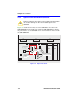
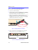
c. Verify that the RJ45 connectors on the twisted pair segment have
the proper pinouts (Figure 3-11 and Figure 3-12) and check the
cable for continuity. Typically, a crossover cable is used between
a switching or hub device and an end user (computer). A
straight-through cable is used between hub devices.
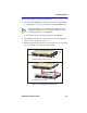
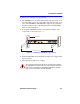
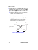
Figure 3-11 Crossover Cable RJ45 Pinouts
TO TO
SSR600 Ethernet Port Other Device Port
RX+ 1 1 RX+
RX- 2 2 RX-
TX+ 3 3 TX+
TX- 6 6 TX-
RJ45 to RJ45
NOTE:
RX+/RX- and TX+/TX-
must share a common
color pair.