
Installation guide


SSR-600 Installation Guide 4-1
CHAPTER 4
TROUBLESHOOTING, SWITCHES, AND
LED INDICATIONS
This chapter is used to aid in determining hardware indications of
operation and problems, and switch settings.
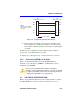
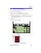
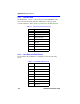
Figure 4-1 shows the front panel LEDs for the SSR-600. Table 4-1,
Table 4-2, and Table 4-3 describe LED states.
Table 4-4 describes switch positions.
If you are having difficulty installing and configuring the SSR-600,
perform the following steps:
• Review Chapter 3 (Installation).
• Verify that power has been applied to the SSR-600.
• Check that all cables and connectors have been attached properly.
Figure 4-1 SSR-600 Front Panel LEDs
RESET
PWR
CPU
LNK
STS
SPD/100
XMT
RCV
SPD/100
XMT
RCV
10/100 10/100
ETHERNET 1 ETHERNET 2
WIDE AREA 2WIDE AREA 1
TELCO TELCO
CONSOLE
FAST ETHERNET
SPD/100 (Speed)
XMIT (Transmit)
RCV (Receive)
Recessed Reset Button
PWR (Power)
CPU (Processor)
LNK (Link)
STS (Status)