SAMSUNG COLOR LASER PRINTER CLP-510/XBH Basic Model : CLP-510/CLP-510N SERVICE SAMSUNG COLOR LASER PRINTER Manual CONTENTS 1. Precautions 2. Reference Information 3. Specifications 4. Summary of product 5. System Outline 6. Disassembly and Reassembly 7. Alignment and Adjustments 8. Troubleshooting 9. Exploded Views and Parts List 10. Block Diagram 11.
Precautions 1 1. Precautions In order to prevent accidents and to prevent damage to the equipment please read the precautions listed below carefully before servicing the printer and follow them closely. 1.1 Safety Warning (1) Only to be serviced by appropriately qualified service engineers. High voltages and lasers inside this product are dangerous. This printer should only be serviced by a suitably trained and qualified service engineer.
Precautions 1.2 Caution for safety 1.2.1 Toxic material This product contains toxic materials that could cause illness if ingested. (1) If the LCD control panel is damaged it is possible for the liquid inside to leak. This liquid is toxic. Contact with the skin should be avoided, wash any splashes from eyes or skin immediately and contact your doctor. If the liquid gets into the mouth or is swallowed see a doctor immediately. (2) Please keep toner cartridges away from children.
Precautions 1.2.3 Handling Precautions The following instructions are for your own personal safety, to avoid injury and so as not to damage the printer (1) Ensure the printer is installed on a level surface, capable of supporting its weight. Failure to do so could cause the printer to tip or fall. (2) The printer contains many rollers, gears and fans. Take great care to ensure that you do not catch your fingers, hair or clothing in any of these rotating devices.
Precautions 1.2.5 Disregarding this warning may cause bodily injury (1) Take care - some parts may be hot. The fuser unit works at a high temperature. Use caution when working on the printer. Wait for the fuser to cool down before disassembly. (2) Take care not to trap fingers or hair. Take care when using a printer. It contains many rotating parts. Ensure that fingers, hair, clothing etc. do not become caught in the mechanism as this could cause injury. (3) When you move the printer.
Precautions 1.3 ESD Precautions Certain semiconductor devices can be easily damaged by static electricity. Such components are commonly called “Electrostatically Sensitive (ES) Devices”, or ESDs. Examples of typical ESDs are: integrated circuits, some field effect transistors, and semiconductor “chip” components. The techniques outlined below should be followed to help reduce the incidence of component damage caused by static electricity.
Precautions MEMO 1-6 Service Manual
Reference Information 2 2. Reference Information This chapter contains the tools list, list of abbreviations used in this manual, and a guide to the location space required when installing the printer. A definition of tests pages and Wireless Network information definition is also included. 2.1 Tools for Troubleshooting The following tools are recommended safe and easy troubleshooting as described in this service manual. • DVM(Digital Volt Meter) Standard : Indicates more than 3 digits.
Reference Information 2.2 Acronyms and Abbreviations The table below explains the abbreviations and acronyms used in this service manual. Where abbreviations or acronyms are used in the text please refer to this table.
Reference Information LCD Liquid Crystal Display PWM Pulse Width Moduration LED Light Emitting Diode Q’ty Quantity LSU Laser Scanning Unit RAM Random Access Memory MB Megabyte RCP Remote Control Panel MHz Megahertz ROM Read Only Memory MPBF Mean Prints Between Failure SCF/SCT MPF/MPT Multi Purpose Feeder/Multi Purpose Tray Second Cassette Feeder/Second Cassette Tray SMPS Switching Mode Power Supply NIC Network Interface Card SPGP NPC Network Printer Card Samsung Printer Gra
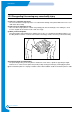
Reference Information 2.3 Select a location for the printer • Leave enough room to open the printer trays, covers, and allow for proper ventilation.
Reference Information 2.
Reference Information 2.5 Wireless LAN • This product can be used with a wireless LAN, (this is an option.) - The wireless LAN function uses radio technology, instead of using LAN cable, to connect to an access point for printing.
Specifications 3 3. Specifications Specifications are correct at the time of printing. Product specifications are subject to change without notice. See below for product specifications. 3.
Specifications 3.2 Controller Specification Items Processor (CPU) Memory Emulation Operating System Interface Interface switching Interface time-out Font Color Management Descriptions Samsung SPGPm (CLOCK SPEED 120Mhz), 32-bit RISC core (ARM 946ES) FLASH ROM (PROGRAM) : 8MB flash *RAM : 64MB (Expandable to 320MB : With Option Option DIMM module : 64/128/256MB 100Pin SDRAM DIMM (Samsung Printer Only) EEPROM (NVRAM) : 1024bytes SPL-Color Win 95/98/ME/NT4.
Specifications 3.5 Consumable & Maintenance Items Items Periodic Replacing Parts Toner Cartridge(Black) Toner Cartridge(Cyan) Toner Cartridge(Magenta) Toner Cartridge(Yellow) OPC Unit ITB Unit(T1 Roller) Waste Toner Tank Fuser Unit Transfer Roller(T2 Roller) Option SCT (Second Cassette Tray) Network Printing 802.
Specifications 3.6 Paper handling Specifications 3.6.1 input Paper Size Paper Paper size 1st Cassette 2nd Cassette MP tray Duplex A4 210 X 297 mm O O O O Letter 216 X 279 (8.5 X 11") O O O O Folio (Legal13") 216 X 330 (8.5 X 13") O O Legal (Legal14") 216 X 356 (8.5 X14") O O Executive 184 X 267 (7.25 X10.5") O Statement 140 X 216(5.5 x8.5") O ISO B5 176 X 250 O JIS B5 182 X257 O A5 148.5 X 210 O A6 105 X148.5 O Com-10 Envelope 105 X 241 (4.15 X 9.
Summary of product 4 4. Summary of Product This chapter describes the functions and operating principles of the main components. 4.1 System Structure 4.1.1 Main Parts of System Deve Cover HVPS DEV. - Black DEV. - Yellow DEV. - Magenta LSU DEV.
Summary of Product >> Front View Panel PBA Waster Toner Sensor Deve OEM PBA Waster Toner Motor >> Rear View Deve Drive Deve Drive PBA Fan Main Drive Duplex Cover Open S/W Deve Cover Open S/W SMPS Main Conrtoller PBA 4-2 Service Manual Samsung Electronics
Summary of product 1) OPC Unit Images are created on the OPC unit using an electro-photographic process. The unit consists of:* OPC Drum * Waste Toner Ass'y used to collect waste toner remaining on the OPC drum, * Charge Roller Assy 2) ITB Unit ITB stands for Image Transfer Belt. An image developed on the OPC Drum is transferred first to the ITB. This is called the T1 Transfer (Primary Image Transfer). Images are built up in layers on the ITB.
Summary of Product 6) MPT (Multi Purpose Tray) The Multi-Purpose Tray not only feeds general printing paper but is also used for many other kinds of paper such as those paper sizes not supported by the cassette, envelopes, OHP, etc. > Spec.
Summary of product 13) Main Drive Unit This motor drives, by way of a gearbox, the OPC unit, ITB unit, feeder unit, fuser unit, exit unit and duplex unit. > Spec. * Power : 20W Max (24V) * Drives : OPC unit, ITB unit, Fuser, Feeder, Duplex unit, Exit unit 14) DEVE Drive Unit This motor drives, by way of a gearbox, the toner cartridges and ITB cleaning cam. > Spec.
Summary of Product 4.1.2 Motor & Fan Layout 1. Main Motor 2. DEVE Motor Fan 4. Waste Toner Motor NO. 4-6 Name Description 1 Main Motor Drives the OPC unit, ITB unit, feeder unit, fuser unit, exit unit and duplex unit. 2. DEVE Motor Drives C, M, Y and K toner cartridges and ITB cleaning cam. 3. Fan Forces cold air into the printer and takes out heat from the fuser. 4. Waste Toner Motor Transfers collected waste toner from the OPC drum and ITB to the waste toner tank.
Summary of product 14.1.3 Clutch & Solenoid Layout Duplex Solenoid ITB Cleaning Clutch K, Y, M) Cartridge Solenoid(C, M, K) T2 Home Clutch Black Deve Clutch Yellow Deve Clutch Magenta Deve Clutch Cyan Deve Clutch Feed Regi Clutch MP Pick_up Solenoid Pick_up Solenoid >>Solenoid NO. 1. Name C DEVE solenoid Description Controls the High Voltage supply to the cyan cartridge. 2. K DEVE solenoid Controls the High Voltage supply to the black cartridge. 3.
Summary of Product >>Clutch NO. Name Description 1. Yellow DEVE clutch Controls Yellow color toner cartridge drive 2. Magenta DEVE clutch Controls Magenta color toner cartridge drive 3. Cyan DEVE clutch Controls Cyan color toner cartridge drive 4. Black DEVE clutch Controls Black color toner cartridge drive 5. Feed Regi. Clutch Controls the location of picked-up paper 4.1.4 Sensor & Micro S/W Layout NO. Name Description 1.
Summary of product 4.1.
Summary of Product DIMM U36 OSC3 (Counter Memory) 23.
Summary of product NPC / (W-LAN) Flash Memory Optional 2MB LPEC1 Full Function Engine SPGPm SDRAM Control 64MB Bloc k SDRAM DIMM 34MB~128MB 5 pin UART Panel EEPROM 16x2 LCD 4k bit USB 2.0 1) CPU BLOCK This is the heart of the machine. A 120MHz - 32bit RISC processor is used to manage commands and data supplied by the host. This is converted into a bitmap image which is passed to the engine block for printing. The CPU is also used to control various other devices e.g. the USB 2.
Summary of Product * Direct connection up to 4 Flash ROM banks - Burst capability - Programmable timing per bank - Up to 16MB address per bank (Limited to 8MB per bank when nDREQ0 is enabled) * Direct connection up to 6 I/O banks & 4 DMA I/O banks - Programmable timing per bank - Programmable recovery timing per bank for slow devices - Up to 16MB address per bank (Limited to 8MB per bank when nDREQ0 is enabled) * Direct connection up to 5 SDRAM arrays - SDRAM controller supports PC-66, PC-100 and PC-133 SD
Summary of product * Timer * * * * - 3 Independent Programmable Timers - Watch Dog Timer for S/W Trap and Tone Generator for MFP Application Up to 5 External Interrupts support - High active interrupt signals - FIQ/IRQ Interrupt mode selectable Ethernet Controller (MAC) - Full compliance with IEEE standard 802.3, 802.3u specification - Support 10/100 Mbps data transfer rates - DMA engine with burst modes (4 words burst and 8 words burst are supported) USB 2.0 interface - USB 1.
Summary of Product 3) Memory Block The operating program runs from memory (see below). It is used to store video data and printing jobs from the host. Standard factory fitted memory is 64MB, and can be expanded using a DIMM module mounted in the SODIMM connector. This is a user fit option, DIMMs from 64Mb - 256MB can be used giving a total of up to 320MB of memory. DIMM modules are non standard - only Samsung product should be used.
Summary of product 4.1.6 SMPS (Switching Mode Power Supply) PBA The SMPS unit supplies DC power for driving the whole system, it also contains an AC heater control unit that supplies power to the fuser. 1) DC output - Main controller PBA, OP panel, SCF, Developer driver PBA 2) AC output -Fuser unit (Heat lamp, Thermostat) 3) Output voltage NO Item CH1 CH2 CH3 CH4 1 Channel name +3.3V +5V +24.0V +24.0VF 2 Rated outputting voltage 3.
Summary of Product 4.1.7 HVPS (High Voltage Power Supply) PBA The HVPS PBA uses the 24V created by the SMPS to generate the high voltages used by the charger, supply, T1,T2 and DEVE processes. For bests quality images these high voltages must be , controlled accurately to maintain the print quality. The high voltages produced are supplied to toner, OPC cartridge, ITB unit, and transfer roller.
Summary of product 1) Charging Voltage: Charger * Function : This high voltage is used to charge the surface of the OPC to about -500volt~800volt. * Output voltage : -200V~-2.0KV DC +/- 3% (Duty is changeable, no loading) * Error type :If MHV was not present, the surface of the OPC is not charged. As a result, toner on the developer roller is transferred over to the OPC drum: therefore, black paper could be printed out.
Summary of Product MEMO 4-18 Service Manual Samsung Electronics
System Outline 5 5 System Outline This chapter describes the functions and operating principals of the main components. 5.1 CLP (Color Laser Printing) Process 5.1.1 OPC Drum Unit (Charge Section) The OPC Unit is the image formation unit and it consists of the OPC drum, waster toner assembly, charge roller assembly, etc. (see diagram below).
System Outline 5.1.2 LSU (Exposure) The bitmap image data stream is used to switch the LSU data beam. Where white paper is required the beam is off, where ink is required the beam is turned on. When the laser is on and the beam strikes the OPC drum surface the charge is reduced to -50V, where the beam is switched off the charge on the OPC surface remains at -600V. In consequence a latent image is formed on the drum surface.
System Outline 5.1.3 Toner Cartridge (Development Section) In the development stage toner particles are transferred from the toner cartridge onto the surface of the OPC drum. The OPC drum and the developer roller rotate in opposite directions. Toner on the developer roller is charged to the developing voltage (-370V ± 3%). Toner is attracted to the OPC drum in those areas where the OPC drum surface charge is -50V. Toner is not attracted to those areas of the surface carrying a -600V charge. DEV.
System Outline 2) Developing state of color The page image is built up from each of the 4 colors and transferred to the paper as described below. > Developing sequence: Y, M, C, and K 1) A latent image containing only yellow toner is created on the OPC drum and then transferred onto the ITB. 2) A latent image containing only magenta toner is created on the OPC drum and then transferred onto the ITB to add to the yellow image already in the ITB.
System Outline 5.1.4 Image Transfer Section The toner image formed on the OPC drum is transferred to the ITB (Image Transfer Belt), this is called the primary image transfer. When the final image has been built on the ITB it is transferred onto paper, this is called the secondary image transfer. 1) Structure 1 2 3 4 ITB Home Sensor 5 OPC DRUM DUPLEX Paper Path NO. Name Description 1. Image Transfer Belt Used to build up the 4 color image from the OPC drum.
System Outline 2) Primary Image Transfer A colored page is split into 4 component color parts and developed one color at a time in turn on the OPC (in the order Y, M, C, K). The final image is built up on the ITB by transferring these separate color images from the OPC drum. Image Transfer Belt Image Transfer Roller OPC DRUM DUPLEX HVPS Primary Image Transfer Bias 3) PTL (Pre-Transfer Lamp) It is arrayed LED on PCB Board.
System Outline 4) Secondary Image Transfer The image is built up on the ITB (primary image transfer). This image is then transferred onto paper using the T2 transfer roller (roller transfer system) this process is known as the secondary image transfer. * The HVPS applies the Image Transfer Bias voltage to the Image Transfer Roller (T2), this transfers the image from the belt onto the paper.
System Outline 5.1.5 Fuser (Fusing Section) Toner that has been through the primary and secondary image transfer processes is fixed, semi-permanently, to the paper. The fuser unit consists of heat lamps (2 ea), heat rollers (2 ea), thermistor, and thermostats (2 ea). It melts the toner onto the paper using pressure and high temperature to complete the printing process.
System Outline 5.1.6 Exit After passing through the fuser paper is ejected into the paper exit tray. Any static electrical charge is removed by static discharge brushes. When operating in duplex print mode, after printing the front side of the page, the paper exit roller reverses to feed the paper back into the machine in order to print the second side of the page. 5.1.7 Waste Toner Collection Process Waste toner on the OPC drum and on the image transfer belt is collected into the waste toner tank.
System Outline 5.2 Outline of Engine Firmware The CLP 510/510N use 4 different colored toners (Yellow, Magenta, Cyan, Black) and it is a laser color printer. Engine firmware controls the print processes, driving the print engine, paper feed, developer, fuser, and paper discharge systems. It has both color and mono printing modes.
System Outline 5.2.1 System Initialization The system initialization process is carried out immediately after power on. The following tasks are performed. 1) Initialize ASIC 2) Initialize system variables 3) Initialize a virtual timer 4) Initialize fuser control 5) Initialize ADC 6) Set-up ITB HOME interrupt 5.2.2 Warm-Up In the warm-up stage, the following tasks are performed.
System Outline 5.2.3 Ready 1) Host interface is monitored for print commands 2) Heat control * Target temperature (165°C) * Every 40 seconds, temperature value for the previous 250ms is read and a proportional control process is carried out 3) This is the standby mode entered after warm-up or after completing a print job.
System Outline 5.2.5 Print After sensing the ITB home position the following tasks are performed, Send Psync signal to controller -> Operates virtual timer for each color(Vdata) -> Forms latent image on OPC drum -> Supplies toner on OPC drum -> Transfers image to ITB (T1 ) -> Pickups a paper -> Transfers image to a paper (T2) 1)Check ITB Home (Treated by Home interrupt): It is designed to detect ITB HOME every 3 seconds. a) ITB Home sensing b) If a test mode is set up, a test pattern is printed.
System Outline MEMO 5-14 Service Manual Samsung Electronics
Disassembly and Reassembly 6 6. Disassembly and Reassembly 6.1 Precautions When Replacing Parts . . . . . . . . . . . . . . . . . . . . . . . . . . . . . . page(6-2) 6.1.1 Precautions when assembling and disassembling . . . . . . . . . . . . . . page(6-2) 6.1.2 Precautions when handling PBA . . . . . . . . . . . . . . . . . . . . . . . . . . . . . . page(6-2) 6.2 Parts for Maintenance and Repair . . . . . . . . . . . . . . . . . . . . . . . . . . . . . . . page(6-3) 6.2.
Disassembly and Reassembly 6.1 Precautions when replacing parts 6.1.1 Precautions when assembling and disassembling * Use only approved Samsung spare parts. Ensure that part number, product name, any voltage, current or temperature rating are correct. Failure to do so could result in damage to the machine, circuit overload, fire or electric shock. * Do not make any unauthorized changes or additions to the printer, these could cause the printer to malfunction and create electric shock or fire hazards.
Disassembly and Reassembly 6.2 Parts for Maintenance and Repair 6.2.1 Replacement interval for parts with a limited life Some of the parts in this printer have a limited life, shorter than that of the whole machine. These parts must be replaced periodically. The table below shows the interval at which these parts should be replaced. The table shows the life of each part, and is measured when using A4 paper.
Disassembly and Reassembly 6.2.2 Printer Cleaning A printer should be regularly cleaned, especially if it is used in a dusty environment. This will ensure that print quality remains high and failure due to contamination of printing services is less likely to occur. * Clean the printer with a soft, lint free, cloth dipped in a "Recommended cleaner" "Recommended cleaner" can be purchased from our service center. (where available) * Do not touch the transfer roller when cleaning the inside of the printer.
Disassembly and Reassembly 6.3 Information Related to Disassembly and Assembly. 6.3.1 Special service parts Never disassemble or adjust the items mentioned, a stock of these items should be maintained. 1) Disassembly of the LSU unit There are no serviceable parts inside the LSU. Alignment of the mirrors is critical. Opening the LSU will allow dust into the laser and significantly reduce print quality. It is very dangerous to operate or service a machine with the LSU open or system interlocks disabled.
Disassembly and Reassembly 6.3.2 Screws used in the printer The screws listed in the table below are used in this printer. Please ensure that, when you disassemble the printer, you keep a note of which screw is used for which part and that, when reassembling the printer, the correct screws are used in the appropriate places. NO DESCRIPTION SEC CODE SPEC NO DESCRIPTION SEC CODE SPEC S1 SCREW-MACHINE 6001-000485 2.
Disassembly and Reassembly 6.3.3 Opening Covers and replacing Consumable parts This section shows you how to open the covers (front cover, DEVE cover, exit cover, and duplex cover) and how to remove and replace the consumable parts (toner cartridge, ITB unit, and OPC drum). >> Consumable parts removal 1) Pull the side handle to open the DEVE cover and then press down firmly until the toner cartridges are ejected.
Disassembly and Reassembly 3) Open the exit cover by pressing the cover open button. Exit Cover Push Deve Cover Caution: Before opening the exit over completely open the DEVE cover until it is at right angles to the main frame and the toner cartridges are ejected 4) Remove the ITB unit by releasing the ITB lock levers on both sides of the unit.
Disassembly and Reassembly 5) Remove the OPC drum by carefully lifting the unit using the handle provided. Take care to ensure that the OPC drum surface is not scratched or damaged. Do not touch the surface of the drum when lifting the drum handle or when removing the drum. OPC Drum Caution: The surface of the OPC drum could be damaged if the OPC drum is exposed to direct sunlight for more than 5 minutes.
Disassembly and Reassembly 6.3.4 Replacing the Waste Toner Tank >> Removing the waste toner tank 1) Push the top corners of the front cover to release the cover catches. PUSH 2) Lift the hook at the top of the waste toner tank and gently pull the top edge of the waste tank forward. Lift the tank out. PULL Caution: Be careful not to let toner spill from the waste toner tank.
Disassembly and Reassembly 3) Remove the Toner Caps from the side of the tank and fit them to the tank inlets as shown below Toner Cap 4) Fit a new waste toner tank.
Disassembly and Reassembly 6.4 Disassembly Procedure 6.4.1 Top cover and Front cover 1) Remove the cassette. Cassette 2) Open all of the covers in the following order:- Duplex cover - DEVE cover - Exit cover (Refer to 6.3.
Disassembly and Reassembly 3) Release 2 screws (4*10 silver). Screw Top Cover Screw 4) Take out the Top Cover as shown below.
Disassembly and Reassembly 5) Push both of the top corners to release the catches and open the front cover and then remove the waste toner tank. (Refer to 6.3.4) PUSH 6) Lift the hook at the top of the waste toner tank and gently pull the top edge of the waste tank forward. Lift the tank out. Caution: Remember to fit the Toner Caps.
Disassembly and Reassembly 7) Release 7 screws (3*10 silver) located inside the front cover. Release 2 screws (3*10 silver) located on the top of the front cover. Screw Screw Screw Screw Screw Screw Screw Screw Screw 8) Release 2 hooks on the right and the left side with a flat bladed screwdriver and then remove the front cover. Take care to disconnect one harness connected to the frame.
Disassembly and Reassembly 6.4.2 OP Panel Ass’y >> Before disassembling it: Remove the front cover. (Refer to 6.4.1) 1) Release 4 screws ('A' below 3X8 gold) and take out the OP panel ass'y (Panel PBA). 2) Release 7 screws ('B' below 3X8 black) from the Panel PBA and remove the panel PBA. 3) Release 1 screws ('C' below M2.6X6 gold) from the LCD and then take out the LCD.
Disassembly and Reassembly 6.4.3 Rear Cover >> Before disassembling it: *Open the duplex cover, the DEVE cover and the exit cover. (Refer to 6.3.3) Remove the top cover. (Refer to 6.4.1) 1) 1) Remove 10 screws.
Disassembly and Reassembly 2) Take out the Rear Cover as shown below.
Disassembly and Reassembly 6.4.4 Duplex Cover Ass'y and Transfer Roller (T2) >> Before disassembling it: * Open the duplex cover, the DEVE cover and the exit cover. (Refer to 6.3.3) * Remove the front cover and top cover. (Refer to 6.4.1) * Remove the rear cover. (Refer to 6.4.3)1) 1) Release 2 hinge screws (3*10 silver) - one on each side of the duplex unit. Screw 2) Remove the duplex cover ass'y by pulling it in the direction shown by the arrows in A and B below. * A: Lift up the left side section.
Disassembly and Reassembly 3) Release 4 hooks on the right and left side with a flat bladed screwdriver and then remove the duplex ass'y.
Disassembly and Reassembly 6.4.5 Fuser 1) Open the DEVE cover Pull Caution: Before opening the exit cover, completely open the DEVE cover until it is at right angles to the main frame and the toner cartridges are ejected 2) Open the exit cover.
Disassembly and Reassembly 3) Release 5 screws (3*10 silver) and then remove the harness cover. Harness Cover Screw Screw Screw Screw Screw 4) Remove one harness. Harness 5) Remove the fuser by holding both sides of the fuser and then pulling the fuser upwards.
Disassembly and Reassembly 6.4.6 Exit Cover >> Before disassembling it: * * * * Remove Remove Remove Remove the the the the front cover (Refer to 6.4.1) rear cover (Refer to 6.4.3) duplex cover (Refer to 6.4.4) fuser (Refer to 6.4.5) 1) Support the Exit Cover and remove the 2 screws (4*10 Silver) indicated using a long blade screwdriver from inside the OPC cavity. Remove the Exit Cover. Screw Screw 2) Remove the exit cover.
Disassembly and Reassembly 6.4.7 SMPS and Main PBA >> Before disassembling it *Remove the rear cover (Refer to 6.4.3) 1) Release 5 screws (3*6 machine screw, gold) from the main PBA bracket.
Disassembly and Reassembly 2) Release 4 screws from the SMPS. Release one screw (3*10 silver) from the harness guide. A: Right side 2EA (3 * 6 Gold) B: Left side 1EA (3 * 10 Silver) C: Bottom 1EA (4 * 10 Silver) Screw B Screw A A SMPS Screw C Screw 3) Remove 4 harnesses from the SMPS.
Disassembly and Reassembly 4) Remove all harness connected to the main PBA. 5) Release 5 screws (3*6 machine screw, gold) from the main PBA and then remove the main PBA. 6) When replacing the Main PBA the Counter memory chip (U36) must be transferred to the new PBA.
Disassembly and Reassembly 6.4.8 Fuser Fan >> Before disassembling it: * Remove the top cover (Refer to 6.4.1) * Remove the rear cover (Refer to 6.4.3) * Remove the main PBA bracket. (Refer to 6.4.7) 1) Release 3 screws (3*10 silver) remove one harness from the main PBA and then take out the fuser fan.
Disassembly and Reassembly 6.4.9 Main Drive Ass’y >>Before disassembling it: * * * * Remove Remove Remove Remove the the the the rear cover (Refer to 6.4.3) fuser (Refer to 6.4.5) SMPS (Refer to 6.4.7) fuser fan (Refer to 6.4.8) 1) Remove all harnesses from the harness guides. 3) Look inside the OPC drum cavity and locate the T2 cam. Remove the washer using tweezers and then remove the T2 cam.
Disassembly and Reassembly 4) Remove the washer using tweezers and then remove the OPC gear and pin. (The OPC gear can be found inside the printer after removing the OPC drum unit. Take care that the pin is not lost as you remove the gear.) Pin-Drive Gear-Drive Washer-Plain Caution : Please don’t lose the Pin-Drive 5) Remove the motor harness. Release 5 screws (3*10 silver) and then take out the main drive ass'y.
Disassembly and Reassembly 6.4.10 HVPS (High Voltage Power Supply) >>Before disassembling it: * Disassemble the front cover & top cover (Refer to 6.4.1) * Disassemble the rear cover (Refer to 6.4.3) * Disassemble the main PBA bracket (Refer to 6.4.7.) 1) Remove one harness from the main PBA CN7 HVPS T1 CHARGER T2 SUPPLY USB CN1(to Deve Driver) 2) Remove one harness and 4 high-voltage harnesses from the HVPS.
Disassembly and Reassembly 3) Remove 5 screws (3*6 machine screw, silver) and then remove the HVPS.
Disassembly and Reassembly 6.4.11 Deve drive ass’y >>Before disassembling it: * Disassemble the rear cover (Refer to 6.4.3) * Disassemble the main PBA (Refer to 6.4.
Disassembly and Reassembly 3) Separate the harness from the DEVE motor. Motor Harness 4) Release 5 screws (3*10 silver) from the DEVE drive ass'y. Remove 4 harnesses connected to the DEVE drive PBA and then remove the DEVE drive ass'y.
Disassembly and Reassembly 6.4.12 Deve drive PBA and DEVE cover open S/W >>Before disassembling it: * Disassemble the rear cover (Refer to 6.4.3) * Disassemble the main PBA (Refer to 6.4.7) * Disassemble the main PBA bracket (Refer to 6.4.7.2) 1) Release 1 screw (3*10 silver) and then take out the DEVE cover open S/W. Screw Deve Cover Open S/W 2) Remove all harnesses and 6 screws (3*10 silver) and then take out the DEVE drive PBA.
Disassembly and Reassembly 3) Remove 4 high-voltage terminals.
Disassembly and Reassembly 6.4.13 Deve Drive Motor ITB Cleaning Solenoid >>Before disassembling it: * * * * Disassemble Disassemble Disassemble Disassemble the the the the rear cover (Refer to 6.4.3) main PBA (Refer to 6.4.7) main PBA bracket (Refer to 6.4.7) DEVE drive motor. (Refer to 6.4.7) 1) Release 4 screws (3*6 gold) and then remove the DEVE drive motor. Screw Screw Screw Screw 2) Unplug one harness from the DEVE drive PBA and then remove the ITB cleaning solenoid.
Disassembly and Reassembly 6.4.14 DEVE cover >> Before disassembling it: * Remove all consumption parts (Toner cartridge, ITB unit, and OPC drum) (Refer to 6.3.3) * Disassemble the front cover and top cover (Refer to 6.4.1) * Disassemble the LSU cover. (Refer to 6.4.14) 1) Remove 2 screws (3*10 silver) and then remove the DEVE open link guide. Screw Deve Open Link Guide Screw Deve Open Link 2) Separate the DEVE cover by pulling it in the direction of the arrow.
Disassembly and Reassembly 6.4.15 LSU unit >> Before disassembling it: * Remove the consumable parts (Toner cartridge, ITB unit, and OPC drum) (Refer to 6.3.3) * Disassemble the Deve cover. (Refer to 6.4.15) 1) Release 4 screws (4*10 silver). (Use a short length cross-head screwdriver.) A A Screw Screw A Screw A Screw Caution : When removing the 4 screws labeled “A” you will need to use a short screwdriver. 2) Release one screw (3*8 yellow). (Use a short length cross-head screwdriver.
Disassembly and Reassembly 3) Separate 2 harnesses and remove the LSU unit.
Disassembly and Reassembly 6.4.16 DEVE OEM PBA >> Before disassembling it: * Disassemble the front cover and the top cover. (Refer to 6.4.1) * Remove the Rear Cover (Refer to 6.4.3) * Disassemble the Main PBA Bracket (Refer to 6.4.7) 1) Separate one harness (CN1) from the Main PBA and one harness(CN2) from the DEVE OEM PBA. Remove 6 screws (3*8 black) and then take out the DEVE OEM PBA. Harness Screw Screw Deve OEM PBA Screw Screw Screw Screw 2) Remove 12 terminals.
Disassembly and Reassembly 6.4.17 Waste toner ass’y >> Before disassembling it: * Disassemble a front cover and a top cover. (Refer to 6.4.1) 1) Release 6 screws (3*10 silver). * Upper part: 4 screws * Lower part: 2 screws Screw Screw Screw Screw Screw Screw 2) Remove the waste toner ass'y by first reaching into the OPC cavity and lightly depressing the waste toner receiver whilst at the same time gently pulling the waste toner motor assy away from the set.
Disassembly and Reassembly 3) Release one screw (3*10 silver) and then remove the sensor cover.
Disassembly and Reassembly 6.4.18 MPT(Multi Purpose Tray) >> Before disassembling it: * Disassemble all consumable parts (Toner cartridge, ITB unit, and OPC drum) (Refer to 6.3.3) * Disassemble the front cover and top cover (Refer to 6.4.1) * Disassemble the rear cover. (Refer to 6.4.3) * Disassemble the duplex cover. (Refer to 6.4.4) * Disassemble the SMPS & main PBA. (Refer to 6.4.
Disassembly and Reassembly 6.4.19 Pick-UpAss'y >> Before disassembling it: *Disassemble *Disassemble *Disassemble *Disassemble *Disassemble *Disassemble *Disassemble all consumable parts (Toner cartridges, ITB unit and OPC drum) (Refer to 6.3.3) the front cover and top cover (Refer to 6.4.1) the rear cover. (Refer to 6.4.3) the duplex cover. (Refer to 6.4.4) the SMPS & main PBA. (Refer to 6.4.7) the Erase Lamp. (Refer to 6.4.14) the Waster Toner Ass'y (Refer to 6.4.
Disassembly and Reassembly 3) Remove the 3*8 black screw retaining the Guide Pick-Up plate. Using a small flat bladed screwdriver or similar tool force the brass ground plate off the retaining lugs and bend it upward slightly. Release the Eraser Lamp harness and paper Empty Sensor harness, these pass between the main engine frame and base frame and cannot be removed.
Disassembly and Reassembly 6.4.20 Pick-Up Roller replacement Note It is not necessary to remove the Pick Up Assy in order to replace the Pick Up Roller >> Before disassembling it: *Disassemble all consumable parts (Toner cartridges, ITB unit, Waste Toner Collector and OPC drum) (Refer to 6.3.3) *Disassemble the rear cover. (Refer to 6.4.3) *Disassemble the SMPS (Refer to 6.4.7) 1) Undo 2 screws (3*10 silver) and remove the "Pick-up Solenoid".
Disassembly and Reassembly 3) Turn the set upside down and Release the shaft retaining bearing and slid it away from the roller. Release the Pick Up spring. 4) Push the rollers firmly towards the frame, if necessary rotate the shaft so that the rubbers do not contact the frame. Release the shaft and bush from the end support. Note this support is fragile take great care. Then slide the shaft back away from the frame to remove it. B. Spring A Shaft retaining bearing C.
Disassembly and Reassembly MEMO 6-48 Service Manual Samsung Electronics
Alignment & Adjustments 7 7. Alignment and Adjustments This chapter describes some of the main service procedures including: Using the EDC mode; Clearing paper jam and test patterns. Much of this chapter is also included in the user's guide. 7.1. Paper path and Paper jam 7.1.1 Paper path Exit Sensor EXIT EXITAss’y Unit Duplex Path Fuser Unit ITB DEV. - Black DUPLEX DEV. - Yellow DEV. - Magenta OPC Feed Sensor DEV.
Alignment & Adjustments 7.1.2 Jams 1) Jam0 (Jam in feed area) * After a page was picked up, it was not fed. * Paper does not reach the feed sensor in a certain time. * Feed sensor is faulty and does not detect paper. - FCF pickup error: When a paper is not picked up in the 1st cassette. - SCF pickup error: When a paper is not picked up in the 2nd cassette.
Alignment & Adjustments 4) Jam duplex (Jam in duplex area) * Jam duplex occurs when printing the reverse side of the paper during duplex printing. After printing the front side the duplex solenoid must operate in order to feed the paper back into the duplex path. If the solenoid fails paper may be stuck in the exit roller and is not fully elected into the exit tray Exit Sensor Feed Sensor * If the duplex solenoid operates paper is fed back into the machine.
Alignment & Adjustments 7.2 Jam Removal When a jam occurs while printing a jam message is displayed on the control panel. * Jam0 In Tray 1: Paper jam in the main cassette. * Jam0 In MP Tray: Paper jam in the MP tray * Jam0 Tray2: Paper jam in the SCT (Second cassette tray) * Jam Inside Printer: Jam 1, Paper is jammed inside the printer. * Jam In Exit Area: Jam2, Paper is jammed in the exit area when ejecting paper. * Jam In Duplex Path: While duplex printing, paper is jammed in the duplex unit.
Alignment & Adjustments 7.2.2 Tips for Avoiding Paper Jams By selecting the correct paper types, most paper jams can be avoided. If a paper jam occurs, follow the steps outlined below: • Ensure that the adjustable guides are positioned correctly. • Do not overload the tray. Ensure that the paper is below the paper capacity mark on the right inside the tray. 7.2.3 Jam 0 In Tray 1 If paper is jammed in the paper feed area,'Jam0 In Tray1 ' appears on the display. 1. Using the handle open the right cover. 4.
Alignment & Adjustments 7.2.4 Jam 0 in MP Tray 1 'Jam0 In MP Tray' appears on the display when you are printing using the Multi-purpose Tray and the printer detects either there is no paper or the paper is improperly loaded. 1. If the paper is not feeding properly pull the paper out of the machine.. 2. To resume printing, open and close the right cover. 7.2.5 Jam Inside Printer : Jam1 ‘If paper is jammed inside the printer 'Jam Inside Printer' appears on the display. 1.
Alignment & Adjustments 7.2.6 Jam In Exit Area : Jam2 If paper is jammed in the paper exit area 'Jam In Exit Area ' appears on the display. 1. If a long portion of the paper is visible pull it straight out. If not continue to step 2. 4. Carefully take the jammed paper out of the printer. Fuser 2. Using the handle open the left cover completely. CAUTION : Do not touch the fuser it is hot and could cause burns! The fuser's operating temperature is 180 °C (356 °F).
Alignment & Adjustments 7.2.7 Jam In Duplex Path : Jam Duplex If paper is jammed in the duplex area 'Jam In Duplex Path' appears on the display. 1. Using the handle open the right cover. 3. If you cannot find the jammed paper or there is any resistance removing the paper go to step 4. 4. Using the handle open the left cover completely. 2. Locate the jammed paper and then pull it out gently and slowly to avoid the paper tearing. Close the right cover. The printer resumes printing.
Alignment & Adjustments 6. Locate the jammed paper and then carefully take it out of the printer. 7. Close the top cover and the left cover firmly Fuser CAUTION : Do not try to close the top cover with the left cover closed. This may cause damage to the machine. CAUTION : Do not touch the fuser it is hot and could cause burns! The fuser's operating temperature is 180 °C (356 °F). Take care when removing paper from the machine.
Alignment & Adjustments 7.2.8 Jam In the Optional Second Tray 1. Using the handle open the right cover. 2. Remove the jammed paper in the direction shown. To avoid the paper tearing pull it out gently and slowly. 3. Close the right cover. The printer resumes printing. 7-10 4. If you cannot find the jammed paper in the machine open the Tray2 outer jam cover. 5. Open the inner cover of Tray 2. 6. Pull the jammed paper out in the direction shown. To avoid the paper tearing pull it out gently and slowly.
Alignment & Adjustments 7. Close the two jam covers. Go to step 11. 9. If you see the jammed paper remove the paper from the machine by gently pulling it straight out. 8.Pull the optional tray, Tray 2, out of the printer. 10. Slide the tray back into the printer and close the two jam covers. 11. Open and close the right cover. The printer resumes printing.
Alignment & Adjustments 7.3 Sample Pattern This product provides several printable test patterns for maintenance purposes. These patterns can be used to aid the diagnosis of print quality problems. 7.3.1 Printing a Demo Page Print a demo page to make sure that the printer is operating correctly. 1. Press the Menu button on the control panel until you see “Information ” on the bottom line of the display.. 2. Press the Enter button to access the Menu. 3. Press the scroll button 4.
Alignment & Adjustments 7.4 Checking the Remaining Toner and Others 7.4.1 Checking the Remaining Toner You can check the level of toner left in each cartridge. 1. In ready mode press the Menu button on the control panel several times until you see ‘Setup ’on the bottom line of the display. 2 Press the Enter button to access the menu. 3 Press the scroll button until ‘Maintenance ’ displays on the bottom line.
Alignment & Adjustments 7.5 Understanding the Control Panel The control panel on the top right side of your printer has a display and seven buttons. 7.5.1 Display Buttorns Status Map Display : dispaly the printer status and job in progress. Message Ready Description •The printer is on-line and ready to print. •If you press On Line/Continue ,the printer switches to off-line. Offline •The printer is off-line and cannot print. •If you press On Line/Continue ,the printer switches to on-line.
Alignment & Adjustments 7.5.2 Buttons Message Description When an error occurs,a lamp turns on at the corresponding location on the Status map.An error message appears on the display so that you can locate the error. Status map •Press to switch between on-line and off-line. •In menu mode,press to return to ready mode. The color of the On Line/Continue button indicates the status of the printer. On The printer is on-line and can receive data from the computer.
Alignment & Adjustments 7.5.3 Using Control Panel Menus A number of menus are available to make it easy for you to change the printer settings. You can configure your printer from the printer’s control panel.You can also use the control panel menus while the printer is in use. 1. In ready mode press the Menu button 2. Press the Enter button 3. Press the scroll button 4. Press the Enter button until you see the menu you want on the bottom line of the display. to access the menu.
Alignment & Adjustments 7.6 Periodic Defective Image If an image defects appears at regular intervals on the printed-paper, it is due to a faulty or damaged roller. Refer to the table below and check the condition of the appropriate roller. No Roller Defective image Typical defect 1 OPC Drum same position in each page white spot on black image or black spot 2 Charge Roller 43.96 mm black spot 3 Supply Roller 31.41 mm light or dark horizontal image band 4 Developing Roller 35.
Alignment & Adjustments 7.7 How to use EDC (Engine Diagnostic Control) Mode 7.7.1 EDC Establishment EDC Mode is feature that allows the engineer to check the condition of the print engine. It can check the operating condition of the motors, sensors, solenoids and clutches, measure the High Voltage from the HVPS and check the operation of the fuser and LSU. 7.7.1.1 How to enter the EDC Mode a) Turn on the printer while pressing the "Enter" key. Hold the key until 'Select Test mode' appears in the display.
Alignment & Adjustments 7.7.
Alignment & Adjustments 7.7.2.1 Motor Test This function allows the operation of the various motors to be checked. a) Press the "<" or ">" key until "Motor Test" is displayed. b) Press the "Enter" key to select this function. c) Press the "<" or ">" key until you see the name of the motor you wish to test. d) Press the "Enter" key to run the test. The test is stopped by pressing the "Upper Level" key.
Alignment & Adjustments 7.7.2.2 Solenoid Test This function allows the operation of various solenoids and clutches to be checked. a) Press the "<" or ">" key until "Solenoid Test" is displayed. b) Press the "Enter" key to select this function. c) Press the "<" or ">" key until you see the name of the clutch or solenoid you wish to test. d) Press the "Enter" key to run the test. The test is stopped by pressing the "Upper Level" key.
Alignment & Adjustments 7.7.2.3 Sensor Test This function allows the operation of various sensors to be checked a) Press the "<" or ">" key until "Sensor Test" is displayed. b) Press the "Enter" key to select this function. c) Press the "<" or ">" key until you see the name of the sensor you wish to test. d) Press the "Enter" key to display the sensor status. If the sensor actuator is moved the displayed status will change to reflect the new sensor position..
Alignment & Adjustments 7.7.2.4 LSU & Fuser Test This function allows the Fuser, LSU Motor and Laser Diode to be tested. a) Press the "<" or ">" key until "LSU & Fuser Test" is displayed. b) Press the "Enter" key to select this function. c) Press the "<" or ">" key until you see the name of part you wish to test. d) Press the "Enter" key to run the test. The test is stopped by pressing the "Upper Level" key.
Alignment & Adjustments 7.7.2.6 Test Print This function allows you to test the overall function of the print engine. You can select either a 4 * 4 color bar pattern or a solid color pattern. If the solid pattern is selected 4 pages are printed - one for each color. You can also print the EDC Mode Menu Map. a) Press the "<" or ">" key until "Test Print" is displayed. b) Press the "Enter" key to select this function. c) Press the "<" or ">" key until "Select Tray" is displayed.
Alignment & Adjustments 7.7.2.7 HVPS Test This function allows the HVPS to be tested a) Press the "<" or ">" key until "HVPS Test" is displayed. b) Press the "Enter" key to select this function. c) Press the "<" or ">" key until you see the name of the voltage you wish to test. d) Press the "Enter" key to select the test. e) Press the "<" or ">" key to select the appropriate Duty Cycle and press "Enter" to start the test The test is stopped by pressing the "Upper Level" key.
Alignment & Adjustments MEMO 7-26 Service Manual Samsung Electronics
Troubleshooting 8 8. Troubleshooting 8.1 Procedure of Checking the Symptoms Before attempting to repair the printer first obtain a detailed description of the problem from the customer. Power On Refer to "8.1.1 Basic Check List" OP Panel ON? Ready or Power Save - No Power - LCD Module - Main PBA Indicate "Error Message" Refer to "8.5 Error Message" Print Printing guality is normal? Refer to "8.
Troubleshooting 8.1.1 Basic Check List 1. Check the Power. • Does "Warming Up" appear on the display? --> If not check power cable, switch or SMPS. (see section 8.1.2 below) --> Does the wall socket work? • Do the Motors or other components initialize (listen for main motor, fan and LSU sounds)? --> If not or there are none of the normal startup sounds check cable, switch or SMPS. --> Does the wall socket work? 2. Check the LCD Panel.
Troubleshooting 8.1.2 Initial Inspection 1. Check Power part 1. The printer does not work no matter how long you wait. A. Is the Power Switch (printer and wall socket) turned on ? B. Is the Power Cord connected to the printer correctly ? C. Is the Power cord connected to the wall socket correctly ? D. Is wall socket working ? E. Is the unit rated at the same voltage as the supply ? 2. Does the Fan work when power is turned on? A. Check the connectors on the SMPS. B. Check the fuses in the SMPS. C.
Troubleshooting 8.1.3 Check the length of life of components The length of life of consumable components is displayed either by operating time (% of life) or quantity of output. The printer will not work if any of these parts have exceeded there expected life. When a user replaces any of these consumable parts they must reset the appropriate counter using the maintenance menus (see section 7.4, page 7-13).
Troubleshooting 8.2 Solution of Image Problem - No Image Cause Sequence of Treatment Driver Installation Problem. Try printing a Demo Page. Check that the operating system driver was installed correctly. Toner cartridge contacts dirty or not making good contact or empty Toner Cartridge (when printing a single color image) Check and clean the toner contacts. Re-seat the Toner Cartridge.
Troubleshooting - Toner Smudges on the reverse side. Cause Sequence of Treatment Paper Path is contaminated. Open covers fully and clean the Paper Path. ITB Unit Belt is contaminated. Clean or replace the ITB Unit. Pressure Roller of Fuser Unit is contaminated. Clean or replace the Fuser Unit. - Foggy back ground Cause Sequence of Treatment If the background is contaminated with only one color. Replace the appropriate Toner Cartridge If the background is generally contaminated with all color.
Troubleshooting - Black / White / Colored Lines and Bands Cause Sequence of Treatment Developing process is contaminated. Replace the Toner Cartridge. Replace the OPC Drum. ITB Unit is damaged or dirty Replace the ITB Unit. Fuser Unit is damaged or dirty Clean or Replace the Fuser Unit. Lens Cover of LSU is damaged or dirty. Clean the Lens Cover of LSU. Replace the LSU if the glass is damaged - Offset Image Cause Sequence of Treatment Afterimage on the OPC Replace the OPC Drum.
Troubleshooting - Deterioration of Printing Quality for Specific Color. Cause Sequence of Treatment If the of Toner Cartridge is bad Check or replace the Toner Cartridge. If the alignment betweem the OPC and ITB Units is not carrect. Re-install the OPC and ITB Units. Uneven contact between OPC and ITB or between ITB and T2 roller. Re-install or replace the ITB Unit. Check T2 roller, solenoid and cam operation.
Troubleshooting - Lateral Lines Cause Sequence of Treatment Contamination or damage to rollers. Measure distance between lines. Refer to Table of Circumferences of Rollers. - Mark in same position on every page. Replace ITB Unit Replace OPC Drum - Mark every 75.36 mm Replace T2 roller - Mark every 29.28 mm Replace Toner cartridge Laser Unit damaged Line repeats every 1~2 mmReplace the LSU Unit. Damage or contemination of OPC drum Random line spacingReplace the OPC Drum.
Troubleshooting 8.3 Paper Feeding Problems and Troubleshooting 8.3.1 Top Margin Error. Symptoms : Printing begins at wrong position on the paper. Check and Cause Solution Wrong sensor timing caused by defective feed sensor actuator. Replace the defective actuator 8.3.2 JAM 0 1. Paper has not exited from the cassette. 2. "Jam-0" occurs even though the paper feeds into the printer. Symptoms Check and Cause Solution 1. Check the Feed Solenoid or PickUp using EDS Mode. 1. Replace the Solenoid. 2.
Troubleshooting 8.3.3 JAM1(JAM inside pinter) Symptoms Paper is jammed in front of the Fuser or under the T2 Roller. Check and Cause Solution Exit Sensor Feed Sensor 1. If the paper is jammed in front of or inside the Fuser 1. Replace the SMPS. 2. If the paper is caught in the Exit Roller and the Fuser check the Feed Sensor actuator opens and closes freely. 2. - Re-assembly the Feed Actuator and Spring, or clean the Hinge with a lint free cloth. - Replace the Main PBA. 8.3.
Troubleshooting 8.3.5 JAM Duplex Symptoms Indicated "Jam in Duplex Area" on the LCD indicator. Check and Cause Solution Exit Sensor 1. Paper in the duplex path fails to operate the Feed Sensor. Feed Sensor 2. Paper in the duplex path fails to reach the Feed Sensor because of jamming in the Duplex Path. 1. Replace the Feed Sensor or Exit Sensor. 2. Check that there are no foreign objects or fragments of paper in the Duplex Path. If necessary replace the Duplex Unit. 8.3.
Troubleshooting 8.3.7 Paper rolling in the Fuser. Symptoms Paper is rolled in the Fuser. Check and Cause Solution 1. If the Heat Roller is conteminated. (Background, Hot off set) 1. Replace the Fuser. 2. If “Accordion” folding occurs between the Fuser and the Exit Unit repeatedly. 2. Check if the Paper Guide Ribs on the Exit Unit are damaged or contaminated, and check the condition and operation of the Exit Roller. 3. If the Bearing - Fuser or Gear - Fuser is damaged or melted by excessive heat.
Troubleshooting 8.4 Symptoms of Bad Operation and Troubleshooting. 8.4.1 Fuser Error Symptoms Open Fuser / Over Heat / Low Heat displayed on the LCD Panel. Check and Cause 1. Check the continuity of the Thermostat, AC Wire and Heat Lamp. Solution 1. Replace the whole Fuser assembly if the Thermostat is open circuit, otherwise replace heat lamps as required.. 2. Check the continuity of the Thermistor and thermistor harness / contacts. 2. Replace broken thermistor or cables as necessary. 3.
Troubleshooting 8.4.4 Paper Empty Symptoms LCD shows "Paper Empty" even though paper is ready. Check and Cause Solution 1. Check for a broken or distorted paper empty sensor actuator. Check that the actuator is not jammed 1. Replace the Paper Empty Sensor actuator. 2. Check the sensor connectors and cable harness. Ensure that a signal reaches the main PBA 2. Replace the harness. 3. Use the EDC mode to test the actuator. 3. Replace the Sensor Board. 8.4.5 Paper Empty without indication.
Troubleshooting 8.4.7. Can not sense when the Cover is Opened. Symptoms LCD Indicates "Ready" even when cover is opened. Check and Cause Solution 1. Check if the Hook Lever inside the Duplex Cover is broken or distorted. 1. Replace the Duplex Cover. 2. Check the Cover Open sensor, connectors and cable harness. Ensure that a signal reaches the main PBA 2. Replace the harness or microswitch as necessary. 3. Use the EDC mode to test the actuator. 3. Replace the Sensor Board. 8.4.
Troubleshooting 8.4.10 Curved or Distorted Vertical Lines Symptoms Curved, wavy or distorted vertical lines. Check and Cause Solution 1. Use EDC Mode to test the LSU. Check that the +24VCD signal between the main PBA and the LSU is stable 1. Replace the LSU or Main PBA. 2. Check that the LSU clock is stable. 2. Replace the Main PBA. 8.4.11 Low Toner Symptoms "Ready Replace [Color]" is displayed on the LCD Panel. Check and Cause Solution 1.
Troubleshooting 8.5 Treatment of Error Message. ADC Not Confirm Error The ADC(Analog -to - Digital Conversion) is defective. 1. Turn the printer off, wait 30 secs and then turn it back on. 2. Replace the Main PBA if the same symptoms recur. Cover Open One of the covers is not properly closed 1. DEVE Cover or Duplex Cover is open. Check and close it correctly. 2. Check the condition of the Cover Open Sensor assembly. --> Replace if it is damaged or nor correctly fitted. Dev.
Troubleshooting Engine FuserOver Heat Error The temperature of Fuser is higher than the Printing temperature. 1. Check both of the Thermostats on the Fuser. --> If it is open circuit replace the Thermostat. 2. Check that the Thermostat on the Fuser is properly positioned and assembled. --> Replace the Thermostat if it is not. 3. Check the Harness connected to the SMPS and Fuser. --> Refit the harness or replace if damaged. 4. Check the Fan and the Fan Harness --> Refit or replace as required 5.
Troubleshooting Waste Motor Error This error is caused by open circuit of Waste Motor Harness or the motor stalling due to increased Waste Motor torque during operation. 1. Open the Front Cover and then check if the Waste Toner Tank is full or the waste inlets are blocked with the Waste Toner. --> Replace the Waste Toner Tank and unblock waste inlet feeds. 2. Open the Top Cover and then remove the ITB Unit and OPC Unit and check if the OPC waste toner outlet blocked. 3.
Troubleshooting Invalid Image Transfer Can not communicate with ITB Unit. *This may be caused by a wrong value of OEM Resistor in the OPC Unit. 1. Open the Top Cover and then check that it is correctly locked in position. --> Remove, replace and re-lock the ITB unit. 2. Replace the ITB Unit. 3. If the fault continues after re-fitting the ITB unit several times check the voltage on Pin4 of CN10 on the Main PBA. --> Replace the ITB Harness if the voltage is not correct. 4. Replace the Main PBA.
Troubleshooting Chapter 8. Troubleshooting Jam In Duplex Path Paper is caught while printing side 2. 1. Open the Duplex Cover and then remove the paper. 2. Remove any foreign objects in the Duplex Path. Jam In Exit Area Paper is caught in the Exit Area. 1. Check the Exit Sensor actuator. --> Replace the Fuser if the Exit Sensor actuator is damaged or bent. 2. Check that the Paper Guide Rib of the Output Guide is clean, and not damaged or distorted.
Troubleshooting Memory Overflow Not enough Memory Capacity. The printer has insufficient memory to build the page image. The print process will be cancelled automatically and the printer will return to the Wait Mode. Add more memory to the printer. Page Too Complex The layout of document is to complex. Try to print again after making the layout simpler and erasing any unnecessary images. If the message is appear repeatedly you will need to add extra memory to the printer.
Troubleshooting Press Cont Key Replace T2 Roller The T2 roller is coming to the end of its usable life and will need replacing soon. * Press the [On-Line/Continue] button to continue printing. * Replace the T2 roller when the image quality becomes unacceptable. * You can select if this message will be displayed on the LCD Pane or not. Ready IP Conflict IP address conflict with the address of another device on the network.
Troubleshooting Replace Toner [Color] It occurs when the Toner Cartridge of indicated Color is not installed. *If the Toner Cartridge does not be installed *The value of OEM Resistor be recognized by the value of opened due to the contamination of Contact point. 1. Open the Deve Cover and then check if the Toner Cartridge is installed. 2. Check if the contact point is contaminated. 3. Replace the Toner Cartridge. 4. Replace the OEM PBA, HVPS and Main PBA in order.
Troubleshooting MEMO 8-26 Service Manual Samsung Electronics
9 9. Exploded Views and Parts List (CLP-510/XBH) Exploded drawings and service parts lists are given for items which may be expected to have a higher failure rate. Where a failure occurs you can identify the part in the exploded diagram and, using the parts cross reference number, refer to the appropriate parts list to identify the part number. Note : Parts numbers given here are correct at the time of publication.
Content 9.1 Main Exploded View 9.2 Cover Front Exploded View 9.3 Cover Top Exploded View 9.4 Cover Deve Exploded View 9.5 Exit Ass’y Exploded View 9.6 Duplex Ass’y Exploded View 9.7 Deve-Drive Ass’y Exploded View 9.8 Main-Drive Ass’y Exploded View 9.9 Fuser Ass’y Exploded View 9.10 Cassette Ass’y Exploded View 9.11 SCF Cassette Ass’y Exploded View 9.12 Frame SCF Ass’y Exploded View 9.13 Main Frame Exploded View 9.14 Front Frame Exploded View 9.15 Rear Frame Exploded View 9.16 Base Frame Exploded View 9.
51 35 4 5 6 3 18 57-1 15 20 49-5 2 1 11 14 57 49-3 49-4 49-2 52 49-1 49-3 21 49 17 40 23 58 22 33 38 22 8 9 45 39 26 25 42 7 30 10 29 12 24 43 56-1 13-1 56-2 28 23 40 56 S8 56-3 32 31 13 43-2 37 41 43-1 16 48 19-2 16-4 S9 58 19-1 19 S8 16-1 44 16-2 16-3 9.
9.
9.
9.
9.
9.
10 8 20 19 18 9 1 2 3 4 5 6 7 11 12 0 13 14 15 16 17 9.
8 35 20 14 10 5 37 38 28 33 22 26 33 21 37 23 24 19 11 12 30 27 17 12 36 3 18 25 12 13 15 16 39 4 9 34 31 32 0 6 29 S11 S17 7 2 1 35 S11 9.
9.
9.10.
9.11.
9.12.
9.
9.
S8 17 38 S8 33 5 30 10 25 S8 1 S9 S8 S8 14 36B S8 16 13 34 37 7 23 15 31 3 19 24 34 4 12 1 9 12 S5 1 12 18 28 26 38 36* (36A+36B) 1 8 29 S8 32 6 11 20 1 22 36A 35 S8 S5 2 S8 9.
9.
9.
9.
9.
9.
9.
9.
Parts List Parts List(Model code : CLP-510/XBH) SA : Service Available, SNA : Service not Available Draw# Part Code Description Location SNA 9.1 Main 9.1-1 9.1-2 9.1-3 9.1-4 9.1-5 9.1-6 9.1-7 9.1-8 9.1-9 9.1-10 9.1-11 9.1-12 9.1-12-4 9.1-13 9.1-13-1 9.1-14 9.1-15 9.1-16 9.1-16-1 9.1-16-2 9.1-16-3 6-1-16-4 9.1-17 9.1-18 9.1-19 9.1-19-1 9.1-19-2 9.1-20 9.1-21 9.1-22 9.1-23 9.1-24 9.1-25 9.1-26 9.1-28 9.1-29 9.1-30 9.1-31 9.1-32 9.1-33 9.1-34 9.1-35 9.1-36 9.1-37 9.1-38 9.1-39 9.1-40 9.1-41 9.1-42 9.
Parts List SA : Service Available, SNA : Service not Available Draw# 9.1-45 9.1-48 9.1-49 9.1-49-1 9.1-49-2 9.1-49-3 9.1-49-4 9.1-49-5 9.1-56 9.1-56-1 9.1-56-2 9.1-56-3 9.1-57-1 9.1-57-2 9.1-57-3 9.1-51 9.1-52 Part Code JC72-01147A 6502-001093 JC97-01838A JC64-00093A JC66-00673A 6044-000121 JC61-00843A JC61-00844A JC97-01949A JC72-01150A JC72-01151A JC31-00025A JC63-00271A JC63-00272A JC67-00044A JC72-01176A JC63-00308A Description PMO-COVER SENSOR BASE;CLP-500,HIPS,BLACK CABLE CLAMP;DAWS-3NE,ID11*L34.
Parts List SA : Service Available, SNA : Service not Available Draw# Part Code 9.5-2 9.5-3 9.5-4 9.5-5 9.5-6 9.5-7 9.5-10 9.5-11 9.5-11-1 9.5-11-2 9.5-11-3 9.5-11-4 9.5-11-5 9.5-11-6 9.5-11-7 9.5-11-8 9.5-11-9 9.5-11-10 9.5-11-11 9.5-11-12 9.5-11-13 9.5-11-14 9.5-11-15 9.5-11-16 9.5-11-17 9.5-11-18 9.5-11-19 9.5-11-20 9.5-11-20-1 9.5-11-20-2 9.5-11-22 9.
Parts List SA : Service Available, SNA : Service not Available Draw# 9.6-1-1-13 9.6-1-1-14 9.6-1-1-15 9.6-1-1-16 9.6-1-1-17 9.6-1-1-18 9.6-1-1-19 9.6-1-2 9.6-1-3 9.6-1-4 9.6-1-6 9.6-1-7 9.6-1-8 9.6-1-9 9.6-1-10 9.6-1-11 9.6-1-12 9.6-1-13 9.6-1-13-1 9.9.1-13-2 9.6-1-13-3 9.6-1-13-4 9.6-1-13-5 9.6-1-13-6 9.6-1-13-7 9.6-1-1-20 9.6-1-1-21 9.6-1-1-22 9.6-1-1-23 9.6-1-1-24 9.6-1-1-25 9.6-1-1-26 9.6-1-1-27 9.6-1-1-28 9.6-1-1-29 9.6-1-1-30 9.6-1-1-31 9.6-1-1-32 9.
Parts List SA : Service Available, SNA : Service not Available Draw# 9.7-15 9.7-16 9.7-17 9.7-18 9.7-19 9.7-20 9.7-21 Part Code 6044-000125 JC31-00021A 6003-000301 JB70-00168A JC66-00465A 6031-001255 JF68-10532B Description Location SNA RING-E;ID4,OD9,T0.6,PASS,STSC MOTOR DC-MAIN(BLDC);50M8432021,CLP-500,1 SCREW-TAPTITE;BH,+,S,M4,L6,ZPC(YEL),SWRC ICT-PIN ADF;SCX-1110F,STS303,D2.0,-,-,-, GEAR-DEVE DRIVE 2_Z20;CLP-500,POM,DE8903 WASHER-PLAIN;NYLON,CUTTING,ID5,OD9,T0.
Parts List SA : Service Available, SNA : Service not Available Draw# 9.9-5 9.9-6 9.9-7 9.9-8 9.9-9 9.9-10 9.9-11 9.9-12 9.9-13 9.9-14 9.9-15 9.9-16 9.9-17 9.9-18 9.9-19 9.9-20 9.9-21 9.9-22 9.9-23 9.9-24 9.9-25 9.9-26 9.9-27 9.9-28 9.9-29 9.9-30 9.9-31 9.
Parts List SA : Service Available, SNA : Service not Available Draw# 9.13-1-2 9.13-1-3 9.13-1-4 9.13-1-5 9.13-1-6 9.13-1-7 9.13-1-8 9.13-1-9 9.13-1-10 9.13-1-11 9.13-1-12 9.13-1-13 9.13-1-14 9.13-1-15 9.13-1-16 9.13-1-17 9.13-1-18 9.13-1-19 9.13-1-20 9.13-1-21 9.13-3 9.13-3-4 9.13-3-1 9.13-3-2 9.13-3-3 9.13-3-5 9.13-3-6 9.13-3-7 9.13-5 9.13-5-1 9.13-5-2 9.13-5-3 9.13-5-4 9.13-5-5 9.13-6 9.13-7 9.13-8 9.13-9 9.13-10 9.13-11 9.13-13 9.13-14 9.13-16 9.13-17 9.13-17-1 9.13-17-2 9.13-17-3 9.13-17-4 9.13-17-5 9.
Parts List SA : Service Available, SNA : Service not Available Draw# 9.13-23 9.13-24 9.13-25 9.13-26 9.13-27 9.13-28 9.13-29 9.13-30 9.13-31 9.13-32 9.13-33 9.13-34 9.13-35 9.13-36 Part Code JC63-00165A JC63-00247A JC66-00334A JC66-40911A JC66-40964A JC61-00984A JC72-01141A JC72-01145A JC72-01171A JC97-02138A JC63-00360A JC72-01216A JC47-00007B JC72-01216A Description GROUND-FUSER FRAME;CLP-500,SUS304CSP,T0. SHEET-ERASER LAMP;CLP-500,PC,T0.5,W220.
Parts List SA : Service Available, SNA : Service not Available Draw# 9.14-27 9.14-28 9.14-29 9.14-30 9.14-31 9.14-32 9.14-33 9.14-34 9.14-36 9.14-37 Part Code JC72-01178A 6107-001196 JC72-01184A JC72-01185A JC72-01221A 6107-001199 JC72-01225A JC72-01283A JC92-01631A 6107-001214 Description Location SNA PMO-DEV OPEN PLATE GUIDE;CLP-500,HIPS,BL SPRING-CS;SUS304-WPB,-,PI0.85,D5.65,L21.
Parts List SA : Service Available, SNA : Service not Available Draw# 9.16-2 9.16-3 9.16-4 9.16-5 9.16-6 9.16-7 9.16-8 9.16-9 9.16-10 9.16-11 9.16-12 9.16-13 9.16-14 9.16-15 9.16-16 9.16-17 9.16-18 9.16-19 9.16-20 9.16-21 9.16-22 9.16-23 9.16-24 9.16-25 9.
Parts List SA : Service Available, SNA : Service not Available Draw# 9.18-3 9.18-6 9.18-7 9.18-8 9.18-9 9.18-10 9.18-11 9.18-12 Part Code JC70-00360B JC72-00719A JC72-00729A JC72-01076A JC92-01453A JC72-41191A JC72-41364A JC73-00149A Description Location SNA IPR-GUIDE-P-INPUT;CLP-510,SECC,-,T0.5,-, PMO-ACTUATOR EMPTY;SCX-5100,-,ABS,BLK,HB PMO-SHAFT PICK UP;SCX-5100,PC,BLACK,-,-, PMO-GUIDE PAPER;CLP-500,HIPS,BLACK,-,HB, PBA SUB-P.EMPTY SENSOR;CLP-500,SEC,-,P.
Parts List SA : Service Available, SNA : Service not Available Draw# 9.20-7 Part Code Description JC61-00050A SPRING ETC-ACTUATOR;ML-6060A,SUS304-WPB, Location SNA Z4132 SA I2131 D2090 Z2649 P2135 K4055 S4110 K2893 K2874 T2001 D2091 C3122 S4071 G2092 S0088 D4088 SA SNA SA SA SA SA SNA SA SA SNA SA SNA SNA SNA SNA D2014 D2087 Z2607 K3422 H1250 SA SA SA SA SA SNA SNA SNA SNA SNA SNA SNA SNA SNA SNA SNA SNA SNA SNA SNA SNA SNA SNA SNA SNA SA SNA SA SNA SNA SA SA SA SA SA SA 9.21 ITB Cam Unit 9.
Parts List SA : Service Available, SNA : Service not Available Draw# Part Code 0501-000294 0501-000457 0502-000245 0502-001048 0601-000353 0601-001138 0601-001383 0601-001444 0603-001021 0604-001154 0604-001257 0803-001097 0803-001393 0803-003263 0803-003264 0904-001752 1001-000170 1006-001250 1103-001183 1103-001328 1105-001384 1107-001287 1202-000164 1203-002220 1203-002233 1205-002339 1404-001141 2001-000008 2001-000047 2001-000058 2001-000111 2001-000281 2001-000290 2001-000429 2001-000577 2001-000621
Parts List SA : Service Available, SNA : Service not Available Draw# Part Code 2007-000122 2007-000123 2007-000134 2007-000309 2007-000539 2007-000608 2007-000729 2007-000736 2007-000839 2007-000842 2007-000939 2007-000965 2007-001002 2007-001044 2007-001134 2007-007004 2007-007445 2007-007726 2007-008567 2008-000166 2009-001085 2011-001011 2011-001094 2201-000017 2201-000119 2201-000138 2203-000041 2203-000189 2203-000192 2203-000236 2203-000257 2203-000426 2203-000440 2203-000476 2203-000626 2203-000783
Parts List SA : Service Available, SNA : Service not Available Draw# Part Code 3301-001240 3301-001258 3301-001594 3404-000165 3702-001121 3704-000349 3708-001408 3709-001131 3711-000164 3711-000198 3711-000225 3711-002000 3711-002003 3711-002808 3711-002809 3711-002810 3711-002811 3711-002813 3711-003408 3711-003409 3711-003410 3711-003411 3722-001101 3903-000085 6001-000125 6001-000485 6001-001068 6002-000175 6002-000308 6003-000115 6003-000152 6003-000196 6003-000264 6003-000266 6003-000267 6003-000269
Parts List SA : Service Available, SNA : Service not Available Draw# Part Code 6902-000606 6902-000655 JB13-00004A JB68-00072A JB68-00073A JB68-00916A JB75-10028A JB75-10029A JC02-00017A JC02-00018A JC02-00019A JC02-00020A JC13-00014C JC13-00020A JC33-00011A JC39-00277A JC39-00282A JC39-00284A JC39-00285A JC39-00286A JC39-00290A JC39-00294A JC39-00295A JC39-00306A JC39-00379A JC39-00380A JC39-00382A JC39-00383A JC39-00385A JC39-00388A JC39-40511A JC41-00133A JC41-00166A JC41-00169A JC41-00201A JC41-00202A
Parts List SA : Service Available, SNA : Service not Available Draw# Part Code JC61-00839A JC61-00869A JC61-00977A JC61-00980A JC61-00981A JC61-00982A JC61-00983A JC61-00985A JC61-00986A JC61-00989A JC61-00989B JC62-00091A JC62-00092A JC62-00093A JC62-00094A JC62-00096A JC62-00097A JC62-00098A JC62-00099A JC62-00100A JC62-00101A JC62-00102A JC62-00103A JC62-00104A JC62-00105A JC62-00106A JC62-00107A JC62-00108A JC62-00115A JC62-00116A JC62-00117A JC62-00118A JC62-00122A JC62-00123A JC62-00124A JC62-00125A
Parts List SA : Service Available, SNA : Service not Available Draw# Part Code JC63-00241A JC63-00248A JC63-00278A JC63-00279A JC63-00280A JC63-00281A JC63-00282A JC63-00283A JC63-00284A JC63-00427A JC63-00552A JC63-00570A JC66-00486A JC66-00487A JC66-00490A JC66-00491A JC66-00492A JC66-00493A JC66-00494A JC66-00495A JC66-00496A JC66-00497A JC66-00498A JC66-00499A JC66-00501A JC66-00502A JC66-00503A JC66-00504A JC66-00505A JC66-00506A JC66-00507A JC66-00508A JC66-00509A JC66-00514A JC66-00521A JC66-00542A
Parts List SA : Service Available, SNA : Service not Available Draw# Part Code JC68-01228A JC68-01229A JC68-01230A JC68-01231A JC68-01428A JC68-01483A JC68-01484A JC68-01488A JC68-10914D JC68-10914E JC68-10914F JC68-10914G JC68-10932A JC68-30928E JC69-00640A JC69-00644A JC69-00732A JC70-00050A JC70-00281A JC70-00345A JC70-00347A JC70-00348A JC70-00349A JC70-00350A JC70-00351A JC70-00352A JC70-00354A JC70-00391A JC70-00392A JC70-00395A JC70-00396A JC70-00398A JC70-00399A JC70-00402A JC70-00403A JC70-00434A
Parts List SA : Service Available, SNA : Service not Available Draw# Part Code JC72-01031A JC72-01032A JC72-01034A JC72-01035A JC72-01036A JC72-01037A JC72-01038A JC72-01039A JC72-01040A JC72-01041A JC72-01042A JC72-01043A JC72-01044A JC72-01045A JC72-01046A JC72-01047A JC72-01048A JC72-01051A JC72-01052A JC72-01053A JC72-01054A JC72-01088A JC72-01095A JC72-01114A JC72-01119A JC72-01120A JC72-01121A JC72-01122A JC72-01123A JC72-01124A JC72-01125A JC72-01126A JC72-01127A JC72-01128A JC72-01129A JC72-01130A
Parts List SA : Service Available, SNA : Service not Available Draw# Part Code JC72-01277A JC73-00090A JC73-20902A JC74-10901A JC75-00032C JC92-01450A JC92-01534B JC92-01551A JC92-01551B JC92-01551C JC92-01551D JC92-01569A JC92-01632A JC96-03213A JC96-03274A JC97-01819A JC97-01820A JC97-01821A JC97-01828A JC97-01835A JC97-01836A JC97-01874A JC99-01744Q JC99-01810A JC99-01813A JC99-01824J JG07-20001A JK72-00058A Description Location SPONGE-ITB TOP;CLP-500,URETHAN SPONGE,-, RPR-RCT PAD PICKUP,MP;SCX-5100
Block Diagram 10 10.
Samsung Electronics IEEE1284 USB Panel CN2 NPC(Option) SCF(Option) Sensor(Paper Empty) Sensor(MP_Empty) Sensor(Feed) Solenoid(T1 Clean) Clutch(Feed) Solenoid(Pick up) Solenoid(MP) Solenoid(Duplex) Solenoid(T2 home) Waste toner&Exit Sensor(Temp3) ITB CN1 17 18 19 20 21 22 23 24 14 26 27 28 29 30 31 32 33 34 35 36 37 38 CN3 CN2 CN4 CN9 CN16 CN21 CN31 CN33 CN35 CN23 CN25 CN32 CN24 CN26 CN17 CN15 CN10 CN12 CN11 CN8 CN6 CN13 Engine & Video Controlle
11-2 +24VF +24VF +24VF +24VF AGND AGND AGND AGND +24V +24V AGND AGND +3.3V +3.3V +3.3V +3.3V DGND DGND DGND DGND +5V +5V DGND DGND nFUSERON NC 3 4 5 6 7 8 9 10 11 12 13 14 15 16 17 18 19 20 21 22 23 24 25 26 Signal Name Main BD(CN30) 1 2 Pin 1 26 25 24 23 22 21 19 17 20 15 18 16 14 13 12 11 10 9 7 5 8 3 6 4 2 1 Dir Pin
Samsung Electronics A_WST_AGT +5VL Deve_Crum_SCL Deve_Crum_SDA AGND 4 5 6 7 8 nWST_AGT NC SENSE_AGT 2 3 Signal Name 1 Pin Deve_Crum_SDA AGND +5VL Deve_Crum_SCL A_WST_AGT +24VF nWST_AGT Dir Pin <<- <- Signal Name DC Motor (Waste Agitator) 8 7 6 5 3 1 4 Signal Name AGND Deve OEM Key(CN1) Dir Pin 2 8 Deve OEM Key(CN2) +24VF nWST_AGT Signal Name AGND 2 3 Pin 1 7 Main Board(CN37) DEVE_CRUM_SDA DGND SCL_OUT2 V1 V2 V3 DGND SCL_OUT2 V5 V6 DGND SCL_OUT2 V8 V9 Signal Name V12
11-4 Signal Name nSOL_DEV_3RD NC AGND Pin 1 2 3 Signal Name nSOL_DEV_4TH NC AGND Pin 1 2 3 <- <<- Signal Name <- <<- Signal Name Solenoid(Deve 4th) Dir Pin Deve Drive(CN3) 12d <- <- Signal Name <- Solenoid(Deve 3rd) Dir Pin Deve Drive(CN7) AGND 3 12c NC Signal Name Dir Pin nSOL_DEV_2ND Solenoid(Deve 2nd) <<- Signal Name <- Solenoid(Deve 1st) Dir Pin Deve Drive(CN2) NC AGND Signal Name nSOL_DEV_1ST Deve Drive(CN6) 2 Pin 1 12b 2 3 Pin 1 12a 3 1 2 Pin 13d 3
DATA0 DATA1 DATA2 DATA3 DATA4 DATA5 DATA6 DATA7 nACK BUSY PERROR SELECT nAUTOFD NC DGND AGND 5V1 3 4 5 6 7 8 9 10 11 12 13 14 15 16 17 18 Signal Name nSTB 2 Pin 1 17 Main BD(CN3) Dir Pin Samsung Electronics <<- <<- <- <<- <<- <<- <- <<- <<- <- Signal Name <- IEEE1284 Port 35 36 NC nSELECTIN NC NC nINIT nFAULT 31 32 33 34 DGND DGND DGND DGND DGND DGND DGND DGND DGND DGND DGND DGND Signal Name 30 28 29 26 27 25 23 24 21 22 19 20 Pin Dir Pin <<- <<- <
11-6 +3.3V DGND nNPC_CS DATA(31) DATA(30) DATA(29) DGND DATA(28) DATA(27) DATA(26) DGND DATA(25) DATA(24) nNPC_INT DGND A_ADDR(5) A_ADDR(4) A_ADDR(3) +3.3V NC DATA(23) DATA(22) NC DATA(21) NC DATA(20) A_ADDR(15) DATA(19) A_ADDR(14) 2 3 4 5 6 7 8 9 10 11 12 13 14 15 16 17 18 19 20 21 22 23 24 25 26 27 28 29 30 Signal Name +3.
Samsung Electronics DGND +24VF nCLT_FEED Signal Name 1 2 nSOL_MP NC 3 Signal Name +24VF 2 Pin 1 <<- Signal Name Dir Pin <- <- Signal Name <- Solenoid(MP) Dir Pin 28 Main BD(CN32) Signal Name +24VF nSOL_PICKUP Pin <<- Signal Name Solenoid(Pick up) Dir Pin 27 Main BD(CN25) 1 2 Pin <- <- C lutch(Feed) 3 2 Signal Name <- Sensor(Feed) Dir Pin 1 26 Main BD(CN23) nS_FEED 3 Signal Name +3.
11-8 +5VL DGND nLDON_LSU VDO_LSU+ VDO_LSU- nSH_LSU CLK_LSU nRDY_LSU nSTART_LSU AGND +24V 2 3 4 5 6 7 8 9 10 11 12 Signal Name +5V EN_ERASER A_TEMP2 GNDA Pin 1 2 3 4 *VIDEO- *LD ON *VIDEO+ +5V GND *HSYNC VCC *START GND 3 2 1 Dir Pin 1 <- <<- Signal Name <- PTL(CN1)&Temp 5 3 4 7 *S/H * Motor Driver 1 CLK 2 *READY 6 4 5 2 3 1 Signal Name * LD Part LSU Dir Pin 35 Main BD(CN11) nHSYNC Signal Name 1 Pin 34 Main BD(CN12) 2 Pin 1 DGND Signal Name A_OPC_KEY 37 Ma
3 2 1 22pF 22pF nUSB_RST BG_Y14 nWAIT 10K 10K C280 R237 BG_Y12 BG_Y13 100pF R238 U14 V14 W14 V15 V16 W16 Y16 W15 Y15 W11 Y14 V18 Y12 Y13 V17 W17 U11 BG_V16 BG_W16 BG_Y16 BG_W15 BG_Y15 TEST_LED1 +3.3V 100pF BG_U14 BG_V14 C202 nRST_PANEL DO C C279 C201 DGND +3.
1 3 2 4 6 5 8 7 REVISION RECORD ED NO. A CHANGE PART A 2901-001178 +3.3V NF5 R55 STS104B 1 100 3 4 3 VCC OUT GND 2 NC95 UCLK OUT IN 100nF C84 33pF NOSC2 COS-000607-12.000M NC 1 DGND GND OSC1 DGND 2 2801-003886 ATS-49/U,12MHz,50ppm DGND DGND 2804-001536 C9 C10 18pF 18pF DGND +3.3V B B +3.3V NR8 NR9 12-14 S1=0 S1=0 S1=0 S1=M FRSEL S0=0 S0=M S0=1 S0=0 1 1.2% 0.9% 0.5% U37 0.
1 2 4 3 5 8 7 6 REVISION RECORD ED NO.
2 1 3 4 6 5 7 8 REVISION RECORD ED NO. CHANGE PART A A ADDR(2:13) +3.3V S_DATA(16:31) CN9-1 FX2CA2-60P-1.27DSAL L19 INSTPAR S_DATA(0:15) IN_3.
1 2 3 6 5 4 8 7 ED NO. USB_3.3V USB_3.3VA CHANGE PART REVISION RECORD USB_3.3V A A RA48 10K 7 5 3 1 DGND 63mW RESERVED U27 0 VBUS_2270 nUSB_DACK 1 TEST1 2 TEST2 64 TEST3 17 VDDIO0 32 VDDIO1 38 DACK 39 EOT 40 ALE 10 VDDC0 42 VDDC1 B R345 NR13 20K NR11 DP DN VBUS +3.3V 51 AVDD 62 PVDD 57 VDD 48 VBUS 49 RREF NR12 0 USB_3.3V DA204K 0407-000101 R346 10K [USB_CONN] B 9.
1 2 4 3 8 7 6 5 ED NO.
2 1 4 3 +3.3V 5 RA36 10K CHANGE PART R306 R132 R299 10K 10K 10K 10K R298 R308 10K 10K 63mW 63mW A 8 6 4 2 8 6 4 2 R339 10K A 10K R307 RA33 10K R305 8 6 REVISION RECORD +3.3V 63mW 4 8 ED NO. RA43 10K 2 7 6 +3.
2 1 4 3 6 5 8 7 ED NO. +5V CHANGE PART REVISION RECORD CN14-1 +5VL 35303-0250 A 1 R82 C110 3W 2 0.39 C99 2005-001058 LSU 100nF +5V A 3711-003408 C284 470uF 16V LSU MICRO SWITCH 100nF +3.3V CN12-1 35303-1250 R156 DGND R226 3711-002813 U22-6 1K 100 1 B 13 L34 2 DGND 1K DM7407MX R166 12 nHSYNC B C232 10nF INSTPAR 0803-001393 +5V DGND 3 +5VL R157 DGND +3.3V +3.3V U22-2 10K DM7407MX R241 4 4 3 R288 3.3K nLDON_LSU R289 3.
1 2 3 6 5 4 8 7 REVISION RECORD ED NO. CHANGE PART HVPS CN7-1 A A +24VF DF11-18DP-2DSA(18) 1 SMPS 2 CN30-1 C292 +24VF DF11-26DP-2DSA(22) 3 +5V C57 100nF 100nF 4 U8-1 1 Power TestPoint 2 AGND 5 3 C175 C166 100uF 50V 100nF R254 100 +3.3VA +5VL DM7407MX 6 24VF1 5VL1 3_3VA1 +24V +5V +3.
3 2 1 4 5 7 6 8 ED NO. REVISION RECORD CHANGE PART A A +5V +24VF BLDC1 CN27-1 35303-1050 1 +5V 2 3 4 +5V R201 R200 R199 10K 10K 10K 5 Q13 6 B U25-2 74LCX06M 0803-003264 MMBT2222ALT1 R183 0501-000457 7 B 510 3 8 2 9 4 R277 1 3 nBLDC_START1 510 R181 5.
1 3 2 4 5 6 8 7 ED NO. CHANGE PART REVISION RECORD A A +3.3V WASTE_TONER & EXIT 35303-0750 R111 R104 39 15K 1/4W CN17-1 1 2 +3.3V FEED B DA204K 0407-000101 CN33-1 35303-0350 2 R205 3 100 C125 10nF B C288 +3.3V DGND 3 47K 2 nS_TONER_RX 100 4 1 R204 1 R101 3 D25 +3.3V 100nF +3.3V D16 DA204K 0407-000101 DGND nS_FEED 5 2 DGND 1 C179 R113 47K 10nF 3711-003409 R120 6 DGND nS_EXIT 100 7 DGND DGND 3 C289 C133 10nF 100nF DGND C C DGND MP_EMPT +3.
1 2 4 3 5 6 8 7 ED NO. REVISION RECORD CHANGE PART DUPLEX CN24-1 5045-02A A +24VF C165 +5V A 1 100nF D21 M4 PICKUP_SOL CN25-1 5045-02A D24 M4 3 C212 100nF 3711-000164 R169 100 2 AGND 13 12 100 1 Q8 nSOL_DUP 0803-003264 C154 100nF R152 5.6K AGND U25-1 10 C167 100nF R173 5.6K 74LCX06M DGND 11 1 0501-000010 AGND 14 R168 510 U26-6 510 3 KSD1691-Y 0502-001048 KSC1008-Y 2 C161 100nF AGND Q9 0402-001189 C213 100nF +3.
1 3 2 4 6 5 8 7 CHANGE PART REVISION RECORD ED NO. A A +3.3VA C160 100nF U25-3 74LCX06M 0803-003264 R176 4.7K GNDA 6 +3.3VA 5 nHEATER ITB B +5VL CN10-1 35303-0750 +3.3V +3.3V R174 20K,1/16W 1 D9 2 0407-000101 R177 68 3 0501-000010 8 D22 3 2007-000066 DA204K R83 4.7K 1202-000164 KSC1008-Y 1% 1 R178 nFUSERON 3 2 1 DGND B Q14 U24-1 LM393D 2 1K MMSD914T1 1 4 R170 4.7K R84 2 nS_ITB_HOME 100 GNDA C108 100nF +3.
2 1 3 5 4 6 7 8 ED NO. REVISION RECORD CHANGE PART +3.3VA AMMSD914T1 +3.3VA F7 STS104B 1 3 AMMSD914T1 AMMSD914T1 A C114 C119 100uF 16V B1 A_WST_AGT INSTPAR AN_WST_AGT 100nF L10 INSTPAR A_OPC_KEY A_OPC_KEY R114 R121 R129 C231 GNDA DGND B AN_READ_CHA AN_READ_T2 AN_READ_T1 C147 A_READ_CHA A_READ_T2 A_READ_T1 3301-000325 100K 100K 100K C140 B C134 2 D35 47K,1% 47K +3.3V D34 R99 D33 47K 47K,1% A R267 +3.3VA +3.
1 3 2 4 6 5 7 8 ED NO. CHANGE PART REVISION RECORD +3.
2 1 3 4 5 6 8 7 REVISION RECORD ED NO.
SAMSUNG ELECTRONICS CO., LTD.
SAMSUNG ELECTRONICS CO., LTD.
Bigbang-v1 Power Supply R9 1/2W100mJ +24V 9.10 D13 200V20A L3-1 L5856 R6 1W22J D1 200V1A 7 BD1 600V5A C20 C21 C22 200V1200uF 1W6.8J R46 1 2 4 ZD1 75V R9 C26 50V1uF R44 510J U2 KA431 R53 36J GND D2 1KV1A 5W15mJ L4 L5843 L5 L5844 R59 3 AY-70 L2 C32 100V103J R35 330J 50V1uF C10 R12 1W22J Q7 A709 D8 60V3A ZD4 27V 1 I R21 R22 R23 C13 222J R16 100J VCC 6 R17 10KJ 12 PC3-1 R18 C14 8.2KJ 681J D12 60V3A C15 104K R49 10KJ R50 220J C41 472MX2 50V1uF R51 4.7KJ +5V 0.
R9 1/2W100mJ T1 Bigbang-v2 Power Supply L3-1 R6 1W22J D1 200V1A 7 C3 102 10D561 C9 R46 1W6.8J 400V270uF YW396 AR11KV R10 1 1 2 4 ZD1 150V R8 1W100KJ C26 50V1uF D2 1KV1A 5W15mJ L4 L5843 L5 L5844 D7 R14 3 L2 AY-70 R59 C32 100V103J R35 330J 5096-02C U3 KA431 Q5 A709 R38 1KJ 200V1A R52 12 R23 10KJ C13 222J R16 100J R17 10KJ PC3-1 R18 C14 8.2KJ 681J C15 104K 50V47uF R21 R22 C16 35V1000uF 3 G C29 U4 KA78R05 R49 10KJ R15 10KJ R54 220J R39 220J D9 4148 ZD3 5.
R9 1/2W100mJ T1 Bigbang-v2c Power Supply L3-1 R6 1W22J D1 200V1A 7 C3 102 10D561 C9 R46 1W6.8J 450V270uF YW396 AR11KV R10 1 1 2 4 ZD1 150V R8 1W100KJ C26 50V1uF D2 1KV1A 5W15mJ L4 L5843 L5 L5844 D7 R14 3 L2 AY-70 R59 C32 100V103J R35 330J 5096-02C U3 KA431 Q5 A709 R38 1KJ 200V1A R52 12 R23 10KJ C13 222J R16 100J R17 10KJ PC3-1 R18 C14 8.2KJ 681J C15 104K 50V47uF R21 R22 C16 35V1000uF 3 G C29 U4 KA78R05 R49 10KJ R15 10KJ R54 220J R39 220J D9 4148 ZD3 5.
* This Service Manual is a property of Samsung Electronics Co.,Ltd. Any unauthorized use of Manual can be punished under applicable International and/or domestic law. * This service manual is also provided on the web, the ITSELF system f Samsung Electronics Co., Ltd. http://itself.sec.samsung.co.kr © Samsung Electronics Co.,Ltd. May 2005 Printed in Korea. VERSION NO. : 1.