
Specifications


1
1
1
1
11-1
Samsung Electronics
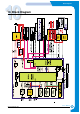
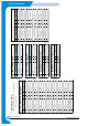
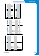
Connection Diagram
Service Manual
11. Connection Diagram
FUSER
LSU
DC Motor
(Waste Agitator)
Solenoid(Deve 1st )
Solenoid(Deve 2nd)
Solenoid(Deve 3rd)
Solenoid(Deve 4th)
Clutch(Deve 1st)
Clutch(Deve 2nd)
Clutch(Deve 3rd)
Clutch(Deve 4th)
FAN
(Fuser)
Panel
CN2
USB
IEEE1284
NPC(Option)
OPC
Eraser
(not use) CN1
PTL & Temp4
CN1
SCF(Option)
Sensor(Paper Empty)
Sensor(MP_Empty)
Sensor(Feed)
Clutch(Feed)
Solenoid(Pick up)
Solenoid(MP)
Solenoid(Duplex)
ITB
Waste toner&Exit
Sensor(Temp3)
BLDC Motor
&Drive
(DEVE)
CN1
BLDC Motor
&Drive
(Main)
CN1
Power(AC Input, 220/110V)
Switch1(Right cover)
Switch2(Left cover)
SMPS
CON4
CON1
CON2
CON3
Switch3(Left cover)
Developer_1st
Developer_2nd
Developer_3rd
Developer_4th
Deve
OEM KEY
CN1
CN2
V1,2,3
V4,5,6
V7,8,9
V10,11,12
HVPS
CN1(1,2)
T1
T2
Charger
Supply
T1 Roller
T2 Roller
Charger Roller
Developer_1st
Developer_2nd
Developer_3rd
Developer_4th
Deve Drive
CN1
CN6
CN2
CN7
CN3
CN8
CN4
CN9
CN5
V1
CN11TAB1
V2
V3
V4
1
2
3
4
5
6
7
8
9
a
11
12a
10
15
16
17
18
19
20
21
22
23
24
14
26
27
28
29
30
31
32
37
36
35
34
33
H.V(T1)
H.V(T2)
H.V(Charger)
H.V(Deve Supply)
9
b
9
c
9
d
12b
12c
12d
13a
13b
13c
13d
H.V(1st Deve Supply)
H.V(2nd Deve Supply)
H.V(3rd Deve Supply)
H.V(4th Deve Supply)
Solenoid(T2 home)
Solenoid(T1 Clean)
* H.V:High Voltage
Power Inlet
&Switch
Sensor(Temp2)
Engine &
Video
Controller
(MAIN BD)
CN7
CN5
CN27
CN25
CN30
CN3
CN29
CN2
CN4
CN9
CN6
CN8
CN11
CN12
CN26
CN16
CN21
CN31
CN33
CN23
CN32
CN24
CN35
CN10
CN28
CN14
CN17
CN15
CN13
38
CN38
CN37