
Specifications


Interface Device View
Device Views EMME/EMM-E6
2-30 Management Module Guide
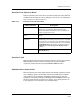
Port Number
Displays the number of a selected port that will be affected by the
configuration changes.
Port Connection
Allows you to chose the appropriate backplane channel from the pull-down
menu. The pull-down menu includes the following selections: Channel A,
Channel B, and Channel C. Individual ports cannot be placed in stand-alone
mode via this menu.
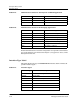
Port Number
This label identifies the port location within the module. The background for
this label is color coded to associate the port with its currently selected
channel. Double-click this label to open the Notes view described in
SPECTRUM Views.
Port Status
This label describes the port activity status. Double-click this label to access
the Port Configuration view described in Chapter 3, Configuration Views.
Port Statistics
Displays the number of frames (packets) transmitted or received by this port.
Double-click this label to access the Performance view described in
SPECTRUM Views.
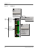
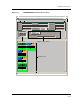
Interface Device View
This section describes the Interface icons and the Interface Options panel
displayed in the Interface Device view. The Interface Device view provides
dynamic configuration and performance information for each interface on this
device. If the configuration changes, SPECTRUM modifies the Device view
after the next polling cycle to reflect the new configuration. This view also
provides a Device icon which allows you to monitor device operation and to
access other device-specific views. Figure 2-6 provides an example of the
Interface Device View.
NOTE
To place only selected ports in stand-alone mode, configure all other ports so
that they are connected to Channel A: those ports will remain connected to
Channel A when stand-alone mode is implemented, and only those ports
connected to channels B or C will be put in stand-alone mode.