
Specifications


9031111 E7 Device Views
2-33
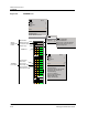
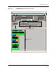
Interface Device View
Interface Icons
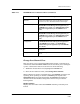
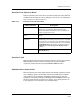
Interface Icon Subviews Menu
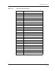
Table 2-18 describes each of the device-specific Icon Subviews menu selections
available from the Interface icon. See Chapter 1, Introduction, for information
on Accessing Device-Specific Subviews.
Interface Label
This label displays the name of the interface. Letters A, B, and C represent the
FNB/backplane channels. Letter D represents the front panel EPIM
connection, and the letter E represents EMM-E6’s BRIM interface.
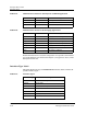
Administrative Status Label
This label displays the status of this interface. The default application for this
view is Bridging. Table 2-19 and Table 2-20 list all possible states and their
corresponding colors for Physical and Bridging Application. To select the
application to be displayed (Physical, Bridging) click the Filter button in the
Interface Options Panel. See the Interface Options panel description later on
in this chapter for more information on the Filter button.
Table 2-18. Interface Icon Subviews Menu
Menu Selection Description
Configuration Opens an Interface Configuration view for the specific
interface type (e.g., Ethernet, FDDI) of the selected
Interface icon. These configuration views are described in
Chapter 3,Configuration Views.
Secondary Address
Panel
Opens the Secondary Address Panel described later in this
chapter.
Protocols
(ATM only)
Allows you to access protocols submenu. The
ATMClientApp menu selection provides access to the ATM
Client Application Configuration View described in Chapter
3, Configuration Views and the Performance view described
in SPECTRUM Views. For other menu selections refer to
the Routing Services Management Module Guide as
applicable.
Model Information Opens the Model Information view described in
SPECTRUM Views.