
Specifications


9031111 E7 Configuration Views
3-15
Port Configuration View (for FDDI)
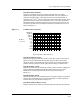
Link Error Rate Estimate
Displays a cumulative long-term average of the bit error rate, which
represents the quality of the physical link. The link error rate estimate is
computed when the port is connected and every 10 seconds thereafter. It
ranges from 10
-4
to 10
-15
and is reported as a whole integer. For example, if the
port’s link error rate estimate is computed to be 10
-5
, the value reported in
this field would be 5, which represents an actual rate of 1,250 bit errors per
second. A lower link error rate estimate indicates a higher bit error rate, as
shown in Figure 3-1.
Figure 3-1. Link Error Rate Estimate
Link Error Monitor Count
Displays the aggregate link error monitor count. This count is set to zero on
station power up and increments each time the port’s link error monitor
detects an error. An increasing link error monitor count usually indicates a
problem with the connectors or the cable between this port and the node.
Link Error Rate Cutoff
Displays the link error rate threshold at which a link connection is flagged as
faulty and the port disabled by SMT. The default link error rate cutoff
threshold is 7, which represents 12.5 bit errors per second (refer to
Figure 3-1).
Link Error Rate Alarm
Displays the link error rate threshold that, if exceeded, generates an alarm for
the port. The default link error rate alarm threshold is 8, which represents
1.25 bit errors per second (refer to Figure 3-1).
Link Error Monitor Reject Count
Displays the link error monitor count of the times the link has been rejected.
.000000125
.00000125
.0000125
.000125
.00125
.0125
.125
1.25
12.5
125
1250
12500
Bit Errors
per Second
Reported Link Error Rate Estimate (n)
45 6789101112131415