MMAC-M5FNB MULTI-MEDIA ACCESS CENTER OVERVIEW AND SETUP GUIDE CABLETRON SYSTEMS, P.O. Box 5005, Rochester, N.H.
NOTICE NOTICE Cabletron Systems reserves the right to make changes in specifications and other information contained in this document without prior notice. The reader should in all cases consult Cabletron Systems to determine whether any such changes have been made. The hardware, firmware, or software described in this manual is subject to change without notice.
NOTICE FCC NOTICE This device complies with Part 15 of the FCC rules. Operation is subject to the following two conditions: (1) this device may not cause harmful interference, and (2) this device must accept any interference received, including interference that may cause undesired operation. Note: This equipment has been tested and found to comply with the limits for a Class A digital device, pursuant to Part 15 of the FCC rules.
NOTICE VCCI NOTICE This equipment is in the 1st Class Category (information equipment to be used in commercial and/or industrial areas) and conforms to the standards set by the Voluntary Control Council for Interference by Information Technology Equipment (VCCI) aimed at preventing radio interference in commercial and/or industrial areas. Consequently, when used in a residential area or in an adjacent area thereto, radio interference may be caused to radios and TV receivers, etc.
CONTENTS CONTENTS CHAPTER 1 1.1 1.2 1.3 1.4 1.5 Using This Manual .................................................................... 1-1 Using the MMAC-M5FNB Manual Set .................................... 1-2 Getting Help ............................................................................... 1-2 The MMAC-M5FNB Multi Media Access Center..................... 1-3 MMAC-M5FNB Features .......................................................... 1-4 CHAPTER 2 2.1 2.2 2.
INTRODUCTION CHAPTER 1 INTRODUCTION The MMAC-M5FNB™ Multi Media Access Center offers maximum flexibility and convenience in the design and operation of your network. The enclosure provides space for one Repeater/Management Module and up to five Media Interface Modules (MIM™); or, by removing one of the five MIMs, you can add a second, load-sharing power supply module. This manual is an installation and reference guide.
INTRODUCTION 1.2 USING THE MMAC-M5FNB MANUAL SET Other manuals have been developed for the Repeater/Management modules and for each MIM that can be installed in your MMAC-M5FNB. These manuals explain how to install the individual modules into the MMAC-M5FNB, how to attach cable segments to the modules, and how to test those segments after they have been installed. Specifications for all modules are included in each manual.
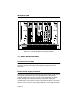
INTRODUCTION 1.4 By Internet mail: support@ctron.com By FAX: (603) 337-3075 By BBS: (603) 335-3358 (4 lines available) THE MMAC-M5FNB MULTI MEDIA ACCESS CENTER The Cabletron Systems MMAC-M5FNB is a complete modular approach to integrated networks. The MMAC-M5FNB supports Local Area Networks compliant to IEEE 802.3, IEEE 802.5, and FDDI standards. It also supports all of the Cabletron Systems Media Interface Modules (MIMs). A variety of IEEE 802.3, IEEE 802.
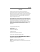
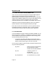
INTRODUCTION SN +5 VOLT TEST -5 VOLT TEST +12 VOLT TEST -9 VOLT TEST COMMON POWER FAIL TRMIM-4A TRMIM-22A TPRMIM-36 CXRMIM SN SN LNK PEN POWER OK FAIL FAULT M5PSM 1 X 2 X 3 X 4 X 5 X 6 X 7 X 8 X 9 X 10 X 11 X 12 X SN SN ERR MGMT 16MB RI RO CRS16 WFLT WRAP FO FLNK 16MB 1 X 2 X 3 X 4 X 5 X 6 X I N 7 X 8 X 9 X 10 X 11 X 12 X R I N G O U T RX ACTIVE UTP TOKEN RING B CLN CLN POK RCV 1 RCV POK 2 3 4 5 6 7 8 9 10 11 12 13 15 16 17 18 19 20 21 22 23 24 25 26 R L C N V K SN RESET C CL
INTRODUCTION supply requires AC power cycling (turn power switch off, then on again) to recover. A FAULT LED on the power supply module indicates when an over current condition has occurred. Note: If you remove, then re-insert, the fan tray with no MIMs installed in the chassis and the power on, you will have to turn each power supply off, then on again to re-start.
INTRODUCTION If a redundant power supply is not desired, a fifth MIM can be installed in the second power supply module slot. Note: The power requirements of some FDDI MIM configurations require dual power supplies. Consult the appropriate manuals for details. Hot Swapping You have the option to “hot swap” power supply modules in the M5FNB. This allows you to remove or insert power supplies without powering down the M5FNB.
INTRODUCTION Rack Mountable Chassis The MMAC-M5FNB chassis can be mounted into a standard 19" (48.26 cm) equipment rack. Separate rack mount brackets are included that allow the unit to be flush mounted or recessed 3" from the front plane of the rack mount unit for safety and ease of network connections. Security Bars A pair of security bars which fit over the knurled knobs that secure the MIMs to the chassis protect the hub from unauthorized removal or insertion of modules.
INSTALLATION REQUIREMENTS AND SPECIFICATIONS CHAPTER 2 INSTALLATION REQUIREMENTS AND SPECIFICATIONS This chapter describes the following: • Site guidelines that must be met before installing an MMAC-M5FNB onto your network • MMAC configuration guidelines • Operating specifications for the MMAC-M5FNB enclosure and power supply module CAUTION: Only qualified personnel should install or service this unit and its modules. 2.
INSTALLATION REQUIREMENTS AND SPECIFICATIONS 2.2 • A USA standard 3 prong power receptacle must be located within 2.13 m (7 ft.) of the site. • The temperature of the location must be maintained between 5° and 40°C (41° to 104°F). Temperature changes of greater than 10°C (18°F) per hour must not occur.
INSTALLATION REQUIREMENTS AND SPECIFICATIONS PHYSICAL M5FNB Dimensions: 14.8" high x 17" wide x 14.8" long (37.6 cm high x 43.2 cm wide x 37.6 cm long) Weight: 17.3 lb (7.8 kg) with fan tray M5PSM Dimensions: 9.5" high x 3" wide x 13.625" deep (24.1 cm high x 7.6 cm wide x 34.6 cm deep) Weight: 6.75 lb (3.0 kg) POWER SUPPLY MODULE REQUIREMENTS The MMAC-M5FNB power supply senses and automatically adapts to the input voltage and frequency.
INSTALLATION REQUIREMENTS AND SPECIFICATIONS Table 2-1. Output Voltage Specifications Output Voltage (Vdc) Minimum Load (amps) Maximum Load (amps) Maximum Power (watts) +5 (±1%) 3 40 200 +12 (±6%) 0 5 60 -5 (±3%) 0 2 10 -9 (±3%) 0 11 99 Note: The maximum power out of each M5PSM power supply will not exceed 300 watts. This unit is intended for indoor use only, and must be used with a two-conductor-plus-ground power supply cord with a minimum HO5VV-F cord, minimum 0.
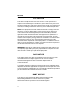
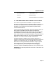
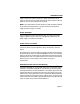
INSTALLATION REQUIREMENTS AND SPECIFICATIONS SN +5 VOLT TEST -5 VOLT TEST +12 VOLT TEST -9 VOLT TEST COMMON POWER FAIL POWER OK FAIL FAULT M5PSM 100-125V ~ 6A 220-250V ~ 3A 50/60Hz Figure 2-1. The MMAC-M5PSM LEDs OK (Power Supply) When lit, this green LED indicates that the power supply module is operating correctly; a signal is also sent to the management/repeater module to indicate that the power supply is functioning properly.
INSTALLATION REQUIREMENTS AND SPECIFICATIONS current condition has been corrected, the power supply requires AC power cycling (turn the power switch off for at least one second, then on again) to recover. Fan Tray LED This LED is green when all the fans are operating properly. The LED turns red when any fan slows to half speed or less, and signals the management/ repeater module that there is a fan tray problem.
INSTALLATION REQUIREMENTS AND SPECIFICATIONS SAFETY Designed in accordance with UL1950, CSA C22.2 No. 950, IEC950, and EN60950. Meets the EMI requirement of FCC Part 15 Class A and EN55022 Class A. Meets the immunity requirements of EN50082-1. This unit must be assembled and used in accordance with the instructions in this manual.
MMAC-M5FNB SETUP CHAPTER 3 MMAC-M5FNB SETUP This chapter contains instructions to help you set up Cabletron Systems’ MMAC-M5FNB. You will not need any special tools or equipment to set up the MMAC-M5FNB, but you must follow all guidelines listed in Chapter 2, Installation Requirements and Specifications. CAUTION: Only qualified personnel should install or service this unit and its modules. 3.1 UNPACKING THE MMAC-M5FNB Before you install the MMAC-M5FNB, you should inspect the unit.
MMAC-M5FNB SETUP 3.2 SETTING UP THE MMAC-M5FNB The following sections list the steps necessary to set up your MMAC-M5FNB, including installing the MMAC-M5FNB in the desired location, inserting the fan tray, and inserting the power supply module(s). 3.2.1 Rack Mounting the MMAC-M5FNB To mount the MMAC-M5FNB in a standard 19" equipment rack: 1.
MMAC-M5FNB SETUP MMAC-M5FNB Multi Media Access Center The Complete Networking Solution™ 1 4 2 5 1.) 2.) 3.) 4.) 5.) 6.) 3 6 Screws (8 total; 4 each side) Rack mount bracket Holes for flush mount Holes for recessed mount Bolts (secure with locking washers) Equipment rack Figure 3-1. Installing the M5FNB into a Rack 3. Insert the screws through the holes on the mounting bracket and into the screw holes on the MMAC-M5FNB. 4.
MMAC-M5FNB SETUP 7. Align the slots on each mounting bracket with the desired holes on the equipment rack. 8. Insert a bolt (item 5) through the slot in each of the mounting brackets and into the threaded holes in the equipment rack (item 6). Secure bolts with locking washers. 9. Tighten the nuts and bolts until the unit is secured to the rack. 3.2.2 Rack Mounting the Cable Tie Tray A cable tie tray is provided with the MMAC-M5FNB to support and organize cables connected to the unit.
MMAC-M5FNB SETUP MMAC-M5FNB Multi Media Access Center The Complete Networking Solution™ Figure 3-2. Cable Tie Tray Installation 3.2.3 Inserting the Fan Tray The MMAC-M5FNB is equipped with a removable fan tray that allows for easy periodic cleaning and/or replacement if a problem occurs with fan operation. To insert the fan tray in the MMAC-M5FNB: 1.
MMAC-M5FNB SETUP 4. When the MMAC-M5FNB is ready to be turned on, observe the LED on the front of the fan tray. This LED should be red for a moment after you turn on the power switch, and then change to green to indicate that all the fans are operating properly. If this LED remains red, it indicates that one or more of the fans is not operating at the proper speed. Check the fan tray to ensure that nothing is interfering with movement of the fans.
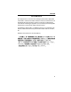
MMAC-M5FNB SETUP MMAC-M5PSMs are installed, the load is evenly distributed; if one power supply fails for any reason other than a shorted DC backplane, the second power supply assumes the load. Note: The power requirements of some FDDI configurations require dual power supplies. The MMAC-M5FNB power supply modules must be installed in the rightmost and leftmost slots of the chassis (Figure 3-4).
MMAC-M5FNB SETUP Install the M5PSM(s) into your MMAC-M5FNB as follows: 1. Unpack the M5PSM by removing it from the shipping box and sliding the two foam end caps off the unit. Save the shipping box and materials in the event the unit must be reshipped. 2. Remove the M5PSM from its protective plastic bag. 3. For the optional redundant power supply module, loosen the knurled knobs securing the panels over the leftmost M5PSM opening in your MMAC-M5FNB and remove the panels.
MMAC-M5FNB SETUP SN SN +5 VOLT TEST -5 VOLT TEST +12 VOLT TEST -9 VOLT TEST COMMON POWER FAIL POWER +5 VOLT TEST -5 VOLT TEST +12 VOLT TEST -9 VOLT TEST COMMON POWER FAIL POWER OK FAIL OK FAIL FAULT FAULT M5PSM 100-125V ~ 5A 220-250V ~ 3A 50/60Hz M5PSM MMAC-M5FNB Multi Media Access Center 100-125V ~ 5A 220-250V ~ 3A 50/60Hz The Complete Networking Solution™ Optional redundant/load sharing power supply Mandatory power supply Figure 3-5. Installing the Power Supply Module(s) 5.
MMAC-M5FNB SETUP To attach the security bars to the chassis: 1. Install all power supplies and MIMs in the M5FNB hub, as desired; be sure to install panels over any empty slots. 2. Place one of the security bars across the top row of knurled knobs securing the modules and panels to the chassis; align the screws in the security bar with the holes in the chassis (as illustrated Figure 3-6, below), and tighten the screws.
MMAC-M5FNB SETUP 3.2.6 Powering Up the MMAC-M5FNB Power up the MMAC-M5FNB as follows: 1. If the MMAC-M5FNB will not be rack mounted, place it on the selected site. 2. Plug a power cord into the power receptacle located on the front of each installed power supply. 3. Plug the power cord(s) into an outlet and move the power switch on each power supply to the on position. 4. Make sure that the Power OK LED is lit.