
Instruction manual

10
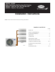
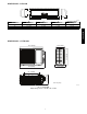
OUTDOOR UNIT INSTALLATION
1. Use a rigid base to support unit in a level position.
2. Locate outdoor unit and connect piping and wiring.
CAUTION
!
EQUIPMENT DAMAGE HAZARD
Failure to follow this caution may result in equipment
damage or improper operation.
Excessive torque can break flare nut depending on
installation conditions.
Piping Connections to Outdoor
Unit
IMPORTANT: Use refrigeration grade tubing ONLY. No
other type of tubing may be used. Use of other types of tubing
will void manufacturer’s warranty.
Make sure there is enough piping to cover the required length
between the outdoor and indoor unit.
Only use piping suitable for high side pressure for both high
side and low side connections.
Piping Guide:
S Do not open service valves or remove protective caps from
tubing ends until all the connections are made.
S Bend tubing with bending tools to avoid kinks and flat spots.
S Keep the tubing free of dirt, sand, moisture, and other
contaminants to avoid damaging the refrigerant system.
S Avoid sags in the suction line to prevent the formation of oil
traps. Insulate each tube with minimum 3/8--in. (10 mm) wall
thermal pipe insulation. Inserting the tubing into the insulation
before making the connections will save time and improve
installation quality.
1. The unit is equipped with multiple pairs of service valves.
Each pair is clearly marked (color and letter) to identify the
indoor unit circuits. In the outdoor unit wiring area, each
indoor unit interconnecting terminal block is marked (letter)
the same as the corresponding pair of service valves. The
indoor units must be piped and wired in matched sets (A to
A; B to B, etc)
2. It is not required to use all of the available fan coil connec-
tions if the application does not require them at the current
time. The system can be expanded at any time.
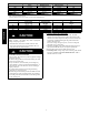
3. Conversion joints are supplied with the outdoor unit. They
are required for certain fan coil combinations. Refer to
chart on page 3 of this document for proper combination.
4. Cut tubing with tubing cutter.
5. Install correct size flare nut onto tubing and make flare con-
nection.
6. Apply a small amount of refrigerant oil to the flare connec-
tion on the tubing.
7. Properly align tubing in with service valve (conversion
joint).
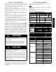
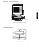
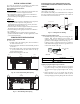
8. Tighten flare nut and finish installation using two wrenches
as shown in Fig. 14.
A07354
Fig. 14 --- Tighten Flare Nut
INSTALL ALL POWER AND INTERCONNECTING
WIRING TO OUTDOOR UNIT
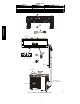
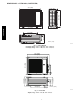
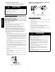
Strong
wind
A07350
Fig. 15 --- High Wind Installation
Outdoor Unit Wiring
Connections
1. Mount outdoor power disconnect.
2. Run power wiring from main box to disconnect per NEC
and local codes.
3. Remove field wiring cover (if available) from unit by
loosening screws.
4. Remove knockouts..
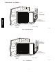
5. Connect conduit to conduit panel. (See Fig. 16)
6. Properly connect both power supply and control lines to ter-
minal block per the connection diagram.
7. Ground unit in accordance with NEC and local electrical
codes.
8. Use lock nuts to secure conduit.
9. Reinstall field wiring cover (size 18k only).
CAUTION
!
EQUIPMENT DAMAGE HAZARD
Failure to follow this caution may result in equipment
damage or improper operation.
S Be sure to comply with local codes while running wire
from indoor unit to outdoor unit.
S Every wire must be connected firmly. Loose wiring may
cause terminal to overheat or result in unit malfunction.
A fire hazard may also exist. Therefore, be sure all wiring
is tightly connected.
S No wire should be allowed to touch refrigerant tubing,
compressor or any moving parts.
S Disconnecting means must be provided and shall be
located within sight and readily accessible from the air
conditioner.
S Connecting cable with conduit shall be routed through
hole in the conduit panel.
38/40GVM