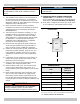
Gas Fired Induced Draft Hot Water Boilers INSTALLATION, OPERATION & MAINTENANCE MANUAL Models (Series C) BW3AAN00042 BW3AAN00075 BW3AAN00112 BW3AAN00150 BW3AAN00187 BW3AAN00225 CAC/BDP 7310 West Morris St. Indianapolis, IN. 46231 P/N# IM-BW3A-07 [240009364, Rev.
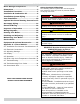
TABLE OF CONTENTS Boiler Ratings & Capacities...................... 3 Safety Symbols & Warnings The following defined symbols are used throughout this manual to notify the reader of potential hazards of varying risk levels. Dimensions ............................................. 4 Installation Procedure ............................. 5 Ventilation & Combustion Air .................. 6 ! Installation System Piping ......................
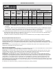
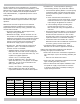
BOILER RATINGS & CAPACITIES Table 1 - RATINGS NATURAL AND PROPANE GASES Vent Diameter (Inches) AFUE High Altitude Input *Mbh To Chimney (Category I) Horizontal Vent (Category III) Model Input *Mbh Heating Capacity *Mbh BW3AAN00042 42 36 31 84.4 38 4 3 BW3AAN00075 75 63 55 83.4 67 4 3 BW3AAN00112 112 94 82 83.0 101 4 3 BW3AAN00150 150 125 109 82.7 135 4 3 BW3AAN00187 187 155 135 82.3 168 4 4 BW3AAN00225 225 186 162 82.
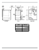
DIMENSIONS Model Width (A) BW3AAN00042 BW3AAN00075 BW3AAN00112 BW3AAN00150 BW3AAN00187 BW3AAN00225 11” (279mm) 14¼” (302mm) 17½” (444mm) 20¾” (527mm) 24” (610mm) 27¼” (692mm) 4
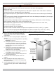
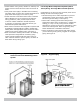
INSTALLATION PROCEDURE ! WARNING NOTICE Follow local regulations with respect to installation of CO detectors. Improper installation, adjustment, alteration, service or maintenance could result in death or serious injury. 10. FOR INSTALLATION ON NON-COMBUSTIBLE 1. The installation must conform to the requirements of 2. 3. 6. 7. 8. 9. 6” 8” 6” Rear Boiler Control Side 5. Figure 1 - Minimum Clearances To Combustible Construction Opposite Side 4.
VENTILATION & COMBUSTION AIR • All Outdoor Air. Provide permanent opening(s) communicating directly or by ducts with outdoors. Provide combustion air and ventilation air in accordance with the section “Air for Combustion and Ventilation,” of the National Fuel Gas Code, ANSI Z223.1/NFPA 54, or Sections 8.2, 8.3 or 8.4 of Natural Gas and Propane Installation Code, CAN/CSA B149.1, or applicable provisions of local building codes. о Two Permanent Opening Method.
INSTALLATION SYSTEM PIPING ! WARNING Burn or Scald Hazard. Discharge line shall be installed to relief valve outlet connection to avoid burns, scalding, or water damage due to discharge of steam and/or hot water during operation. Discharge line shall: • connect to relief valve outlet and piped down to safe point of disposal. Check local codes for maximum distance from floor or allowable safe point of discharge.
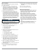
INSTALLATION SYSTEM PIPING Figure 4 - Forced Hot Water Typical Piping With Zone Control Valve Figure 3 - Forced Hot Water Typical Piping 8
INSTALLATION SYSTEM PIPING • Install radiation units (panels, radiators or cabinets) and supply and return mains first then make connections at boiler. • Verify clean water supply is available when connecting cold water supply to water valve. Install sand strainer at pump when water supply is from well or pump.
VENT INSTALLATION Check Your Chimney Chimney must be clean, right size, properly constructed and in GOOD CONDITION. 11. Fasten sections of vent pipe with sheet metal screws to 1. Installation must conform to requirements of the 12. Do not connect to fireplace flue. 13. Do not install damper on this boiler. make piping rigid. Use stovepipe wires to support pipe from above. authority having jurisdiction or, in absence of such requirements, to the National Fuel Gas Code, ANSI Z223.
VENT INSTALLATION Figure 7 - Type B Gas Vent CHECK YOUR CHIMNEY For boilers for connection to gas vents or chimneys, vent installations shall be in accordance with “Venting of Equipment”, of the National Fuel Gas Code, ANSI Z223.1/NFPA 54, or of the Natural Gas and Propane Installation Code, CAN/CSA B149.1, or applicable provisions of the local building codes.
VENT INSTALLATION 5. Test for spillage at the draft hood relief opening after 5 Removing Existing Boiler From Common Venting System When an existing boiler is removed from a common venting system, the common venting system is likely to be too large for proper venting of the appliances remaining connected to it.
OPTIONAL HORIZONTAL VENTING INSTRUCTION Horizontal venting with a power venter is an alternate method of sidewall venting. This boiler is CSA listed for sidewall venting with standard single wall galvanized or Type B vent pipe when using the following power venter kits, which were specifically sized for these boilers: Confirm that installing a power venter is an option allowed by local codes. Follow the specific power venter installation instructions issued with the power venter kits.
GAS SUPPLY PIPING Connecting Gas Piping Gas line enters boiler from right side. Flexible gas connectors must never breach any boiler openings. • Use piping materials and joining methods acceptable to authority having jurisdiction. In absence of such requirements: • USA - National Fuel gas Code, ANSI Z223.1/NFPA 54 • Canada - Natural Gas and Propane Installation Code, CAN/CSA B149.1 • All pipe compound must be resistant to liquefied petroleum gas.
GAS SUPPLY PIPING Table 7- PROPANE GAS Table 6 - NATURAL GAS Length of Pipe - Ft. 20 Pipe Capacity - BTU Per Hour Input Length of Pipe - Ft.
ELECTRICAL WIRING Electric Power Supply Run a separate 115 volt circuit from separate over current protective device 15 ampere circuit in electrical service entrance panel. Connect 115 volt power supply to terminals L1 (HOT) and L2 inside J box. Run 14 gauge or heavier copper wire from boiler to grounded connection in service panel or properly driven and electrically grounded ground rod. ! WARNING Electrical shock hazard.
SEQUENCE OF OPERATION Sequence of Operation - Figure 10, Page 18. 1. Thermostat calls for heat, control relay contacts. 2. Circulator pump is powered through terminals C1 and C2. Control holds off burner and attempts to satisfy thermostat with residual boiler heat. 3. Induced draft blower and transformer primary are powered. 4.
WIRING DIAGRAMS Figure 10 - Control Module Damper is not an option.
STARTING YOUR BOILER ! CAUTION Burn, scald, explosion hazard. Failure to follow these instructions could result in minor or moderate injury. Filling System With Water • Close air vents on all radiation units. Open valves to these units. • Verify boiler and expansion tank drain valves are closed. Air bleed screw on tank drain fitting should be closed. • Open valve in line from boiler to expansion tank. • Open water inlet to your boiler and leave open. • Start with lowest radiation unit.
STARTING YOUR BOILER Operating Instructions. 1. STOP! Read Safety Information on previous page. 2. Set the thermostat to lowest setting. 3. Turn off all electric power to the appliance. 4. This appliance is equipped with an ignition device which automatically lights the burner. Do not attempt to light pilot by hand. 5. Remove burner access panel. ! WARNING If you do not follow these instructions exactly, a fire or explosion may result causing property damage, personal injury or loss of life.
CHECKING AND ADJUSTING Gas Valve Safety Shutdown Test Figure 12 - Automatic Gas Valve ! WARNING Electrical shock hazard. Follow instructions to turn off electric power. Failure to do so could result in death or serious injury. Ignition system safety shutoff device must be tested after placing boiler in operation. With main burners firing, disconnect ignition cable from intermittent pilot control box. Gas valve should shut off main burners.
CHECKING AND ADJUSTING Figure 14 - Main Burner Flame Adjust Thermostat Heat Anticipator Instruction for final adjustment of thermostat are packaged with thermostat. 1. Set Heat anticipator at .2. 2. Check thermostat operation. When set above temperature indicated on thermometer, boiler burners should ignite. Verify thermostat turns off boiler when room temperature reaches selected setting and starts boiler operating when room temperature falls few degrees.
MAINTAINING YOUR BOILER Burners Beginning of heating season visually check pilot and main burner flames. See Figures 13, and 14. Cleaning Your Boiler And Burners Flue passages between sections should be examined yearly and cleaned if necessary. To clean: • Remove burners, pilot, and vent pipe. Safety Relief Valve Test safety relief valve for proper operation. Refer to valve manufacturer’s instructions packaged with relief valve. • Remove top and front jacket panels.
SERVICE HINTS You may avoid inconvenience and service calls by checking these points before you call for service: ! CAUTION WHAT TO DO IF YOU SMELL GAS • Do not try to light any appliance. • Do not touch any electrical switch; do not use any phone in your building. • Immediately call your gas supplier from a neighbor’s phone. Follow the gas supplier’s instructions. • If you cannot reach your gas supplier, call the fire department. IF YOUR SYSTEM IS NOT HEATING OR NOT GIVING ENOUGH HEAT . . .
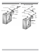
EQUIPMENT & OPTIONAL ACCESSORIES AIR ELIMINATING FITTING (AIR PURGER) Air purger is used to remove excess air from system. It is installed in supply line. It will eliminate air from water before it reaches radiators and bleed off this air. ! WARNING Burn and scald hazard. Safety relief valve could discharge steam or hot water during operation. Install discharge piping per these instructions.
EQUIPMENT & OPTIONAL ACCESSORIES PRESSURE SWITCH Air pressure switch works on negative pressure. When blower comes on air pressure switch operates intermittent pilot and gas valve. Air pressure switch is factory set and will only work when blower operates properly. It will not allow boiler to come on if blower does not generate enough pressure or if venting system is blocked. Factory Pressure Switch Set point: -0.4” wc. for 2-5 section boilers. -0.5” w.c. for 6-7 section boilers.
APPENDIX A - CONTROL MODULE A.1 Installation Environment Considerations A.3 Adjusting Settings To discourage unauthorized changing of settings, procedure to enter adjustment mode is required. To enter adjustment mode, press UP, DOWN, and I buttons (see Figure 1) simultaneously for three seconds.
APPENDIX A - CONTROL MODULE 2. Control determines burner operation is required, A.5 Operation module proceeds to start burner (see state codes list) and heats water in boiler until setpoint temperature is achieved or thermostat is satisfied. . 3. Burner is de-activated, ignition module completes heating cycle, returns to idle and waits for temperature to drop again. 4. Circulator is turned on throughout “Call for Heat.
APPENDIX A - CONTROL MODULE A.6 Boiler High Limit Temperature Controller A.7 Troubleshooting • When water temperature reaches setpoint, controller ends heating cycle. • Following service procedures are provided as general guide. • When water temperature drops below setpoint minus differential, controller restarts heat cycle to re-heat boiler water. • On lockout and retry models, meter readings between gas control and ignition module must be taken within trial for ignition period.
APPENDIX A - CONTROL MODULE Table 2 - Troubleshooting Error Codes Error Code Number Definition Consequence 2 Pressure switch failed to open (stuck closed). Wait for recovery 4 Flame current too low. Check for flame. Non critical alarm 6 Flame sensed out of normal sequence (before opening or after closing gas valve). Soft lockout 18 Gas valve relays welded. Five consecutive soft lockouts. Hard lockout 23 Flame sensed during prepurge ( before gas valve signaled opened).
APPENDIX A - CONTROL MODULE • Recheck ignition sequence as follows. STEP 3: Check spark ignition circuit. Disconnect ignition cable at SPARK terminal on module. — — — — Reconnect main valve wire. Adjust thermostat above room temperature. Verify ignition sequence at burner. If spark does not stop after pilot lights, replace module. — If main burner does not light or if main burner lights and system locks out, check module, ground wire and gas control as described in troubleshooting Error Codes.
CAC/BDP 7310 West Morris St. Indianapolis, IN.