
Operating instructions

33
7.1 General
• Use piping materials and joining methods acceptable
to authority having jurisdiction. In absence of such
requirements:
• USA - National Fuel Gas Code, ANSI Z223.1/NFPA
54
• Canada - Natural Gas and Propane Installation Code,
CAN/CSA B149.1
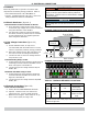
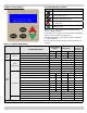
• Size and install gas piping system to provide sufcient
gas supply to meet maximum input at not less than
minimum supply pressure. See Table 10.
• Support piping with hooks straps, bands, brackets,
hangers, or building structure components to prevent or
dampen excessive vibrations and prevent strain on gas
connection. Boiler will not support piping weight.
• Use thread (joint) compound (pipe dope) suitable for
liqueed petroleum gas.
• Provide sediment trap up stream of gas valve.
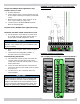
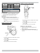
• Install manual main shutoff valve outside of jacket. See
gure 7-2.
7.2 Conversion Kit Instructions
• See Gas Conversion Kit Instructions included with Boiler.
Table 10 - Gas Supply Pressure
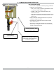
FIGURE 7-2 Manual Main Gas Shutoff Valve Outside
Boiler Jacket
7.3 Leak Check Gas Piping
Pressure test boiler and gas connection before placing
boiler in operation.
•
Pressure test over 1/2 psig (3.5 kPa). Disconnect
boiler and its individual gas shutoff valve from
gas supply system.
•
Pressure test at 1/2 psig (3.5 kPa) or less.
Isolate boiler from gas supply system by closing
manual gas shutoff valve. See gure 7-2.
•
Locate leakage using gas detector, noncorrosive
detection uid, or other leak detection method
acceptable to authority having jurisdiction. Do
not use matches, candles, open ames, or other
methods that can provide ignition source.
•
Correct leaks immediately and retest.
Manual Main Gas
Shutoff Valve
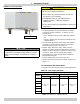
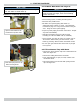
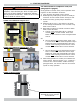
FIGURE 7-3 Gas Shutoff Valve - 050/075/100/150/200
DANGER
Fire Hazard. Do not use matches, candles, open
ames, or other methods providing ignition source.
Failure to comply will result in death or serious
injury.
!
Gas shutoff valve
(shown in closed
position)
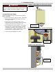
FIGURE 7-4 Gas Shutoff Valve - 299
Gas shutoff valve
(shown in open
position)
7 - GAS SUPPLY PIPING