
User guide


203 Series Industrial Grade 2.5" FlashDrive Product Manual v2.0Cactus Technologies
®
16
t
su
A
t
w
CS0, CS1,
A[2:0]
/DIOWR, /
DIORD
WRITE
D[15:0]
t
h
A
t
dis
(IORD)
t
h
(IOWR)
t
sud
(IOWR)
READ
D[15:0]
t
sud
(IORD)
t
h
(IORD)
t
cyc
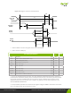
Figure 3-3. Register Transfer To/From Device
1. Device address consists of signals -CS0, -CS1 and -DA(2:0).
2. Data consists of DD(7:0).
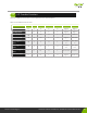
PIO Timing Parameters
Mode
4 ns
Note
tcyc Cycle time (min) 120 1
tsuA Address valid to IORD-/IOWR- setup (min) 25
tw IORD-/IOWR- pulse width (min) 70 1
thA IORD-/IOWR- recovery time (min) 25 1
tsu(IOWR) IOWR- data setup (min) 20
thD IOWR- data hold (min) 10
tsu(IORD) IORD- data setup (min) 20
th(IORD) IORD- data hold (min) 5
tdis(IORD) IORD- data tri-state (min) 30 2
thA IORD-/IOWR- to address valid hold (min) 10
1. tcyc is the minimum total cycle time, tw is the minimum command active time, and trec is
the minimum command recovery time or command inactive time. The actual cycle time equals
the sum of the actual command active time and the actual command inactive time. A host
implementation must ensure that tcyc is equal to or greater than the value reported in the
devices IDENTIFY DEVICE data.
2. This parameter species the time from the negation edge of /IORD to the time that the data
bus is no longer driven by the device (tri-state).