
Owner's manual

Industrial Grade 203 Series PC Card Product Manual v3.0Cactus Technologies
®
15
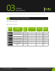
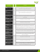
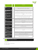
Signal Name Dir. Description
-WAIT
(PC Card I/O Mode)
O
The –WAIT signal is driven by the PC Card to signal to the host to
delay completion of the I/O cycle in progress.
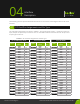
-IORDY (True IDE
Mode, UDMA not
active)
-DDMARDY (TrueIDE
Mode, UDMA write
active)
DSTROBE (TrueIDE
Mode, UDMA read
active)
In TrueIDE Mode, when UDMA protocol is not active, the -IORDY sig-
nal is driven by the PC Card to extend the I/O cycle in progress.
In TrueIDE Mode, when UDMA write protocol is active, this signal is
driven by the device to indicate that it is ready to receive data out
bursts.
In TrueIDE Mode, when UDMA read protocol is active, this signal is
the data strobe sent by the device to the host; data is latched by the
host on both rising and falling edges of this signal.
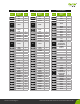
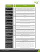
-WE
(PC Card Memory
Mode)
I
This is a signal driven by the host and used for strobing memory
write data to the registers of the PC Card when the card is congured
in the memory interface mode. It is also used for writing the congu-
ration registers.
-WE
(PC Card I/O Mode)
In PC Card I/O Mode, this signal is used for writing the conguration
registers.
Reserved
(True IDE Mode)
In True IDE Mode this input signal is not used and should be connect-
ed to VCC by the host.
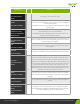
WP
(PC Card Memory
Mode)
Write Protect
O
Memory Mode—The PC Card does not have a write protect switch.
This signal is held low after the completion of the reset initialization
sequence.
-IOIS16
(PC Card I/O Mode)
I/O Operation—When the PC Card is congured for I/O Operation,
Pin 24 is used for the -I/O Selected is 16 Bit Port (-IOIS16) function. A
Low signal indicates that a 16 bit or odd byte only operation can be
performed at the addressed port.
-IOCS16
(True IDE Mode)
In True IDE Mode this output signal is asserted low when this device
is expecting a word data transfer cycle.
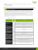
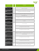
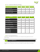
Electircal Specication
4.3.
The following table denes all D.C. Charactaristics for the PC Card Series. Unless otherwise stated,
conditions are:
Vcc = 5V ± 10% or Vcc = 3.3V ± 10%
Ta = -40°C to 85°C