M16 Remote Controlled Microphone Amplifier
M16 Remote Controlled Microphone Amplifier Installation & User Manual
i Table of Contents Table of Contents ................................................i Introduction .......................................................iii Features .............................................................iv Using the M16 Manual ......................................iv Declaration of conformity .................................v 1 Important Safety Instructions ........................1-1 1.1 1.2 1.3 1.4 1.5 1.6 2 Important information .....................................2-1 2.
ii 4 Remote control of the M16 ............................ 4-1 4.1 4.2 4.3 4.4 4.5 4.6 4.7 4.8 4.9 4.10 4.11 4.12 4.13 4.14 4.15 4.16 4.17 4.18 Introduction ..............................................................4-1 RS-485 Communications Protocol........................... 4-1 CADAC RM16 Remote Mic Amp. Controller ........... 4-1 Front Panel ..............................................................4-2 Rear Panel...............................................................
iii Introduction Thank you for purchasing the M16 Remote Controlled Microphone Amplifier from CADAC Electronics plc. CADAC is renowned for supplying arguably the highest quality audio mixing consoles for the world-wide professional audio industry for over 36 years. In all these years the driving force behind the company’s research and development program has been to strive for products that not only provide the exact functionality required but also exceptional audio performance and reliability.
iv Features ■ 16 channels of high performance microphone amplifiers. ■ Ideal solution for touring, broadcast or recording applications ■ ■ ■ ■ ■ ■ ■ ■ when high quality microphone amplifiers are required.Each channel output is provided with an integral 3-way active splitter. Each output is designed to drive over long cable lengths in excess of 500m All channels are fitted with a switchable high pass filter.
v Declaration of conformity The Directives covered by this Declaration 89/336/EEC Electromagnetic Compatibility directive, amended by 92/31/EEC & 93/68/EEC The Products Covered by this Declaration M16 remote controlled microphone amplifier.
vi M16 Microphone Amplifier Revision MA2005-7
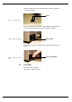
1-1 1 Important Safety Instructions 1.1 Mains Cable The supplied IEC mains cable must be correctly terminated before use. Use only an approved AC plug or power distribution device. Safety ground must be connected at all times. Safety Earth = Green/Yellow Live = Brown Neutral = Blue 1.2 Changing the fuse To avoid the risk of fire, use only the recommended fuse type as indicated in this manual and on the M16. Do not short-circuit the fuse holder.
1-2 Replace the blown fuse with an identical type. See Fuse Types below for further details. Fuses FIG 1-2. Replace the fuse Refit the fuse holder, taking care to align it properly. The guide arm of the fuse holder slots into the power connector assembly. Fuse holder FIG 1-3. Refit the fuse holder Once in place, push the fuse holder home and confirm that it is fully seated. Push in fuse holder FIG 1-4. Push the fuse holder home 1.
1-3 1.4 Servicing There are no serviceable parts contained within the M16. Refer all servicing to your CADAC distributor. 1.5 Do not remove any covers Within the M16 are areas where high and dangerous voltages are present. Removing any covers will invalidate warranty. 1.6 Safety checklist ■ Install in accordance with CADAC’s instructions. ■ Do not place the apparatus on an unstable or uneven surface. ■ Do not insert objects through any apertures.
1-4 M16 Microphone Amplifier Revision MA2005-7
2-1 2 Important information 2.1 Unpacking The packaging for the M16 is designed to safely contain and protect the M16 from the rigours and stresses usually experienced during international shipment. Specially designed mouldings cushion and support the M16, while also providing space to incorporate and protect the optional RM16 and PSU. Space is provided to safely include additional M16 specific items.
2-2 2.2 Operational considerations AC mains voltage The M16 is intended for use throughout the world and therefore the internal power supply allows operation through the following AC mains voltages: Mains voltage: 90v - 250v AC Mains frequency: 50/60Hz AC mains connection The rear panel of the M16 houses the AC mains inlet on an IEC style connector. The mains cable supplied with the M16 is also fitted with a moulded IEC connector.
3-1 3 The M16 Microphone Amplifier 3.1 M16 Front panel 1 2 18 16 3 4 5 17 8 9 10 11 12 13 14 15 7 6 FIG 3-1. M16 front panel layout 1. Channel Number 2. Signal Overload Indicator 3. Signal Present Indicator 4. PFL Switch 5. Mute Switch 6. Headphone Socket 7. Headphone Level Control 8. PFL Level Meter 9. Channel Gain 10.Gain Increment Switch 11.Gain Decrement Switch 12.Polarity Reverse 13.Pad Switch 14.Phantom Power Switch 15.High Pass Filter Switch 16.Remote Indicator 17.USB Indicator 18.
3-2 3.2 M16 Rear Panel 11 1 2 3 4 5 15 6 7 8 9 12 10 13 14 FIG 3-2. M16 rear panel layout 1. Mains Inlet, Fuse and Power switch 2. Ground Stud 3. RS-485 Remote Communications Output Connector 4. RS-485 Remote Communications Input Connector 5. Word Clock BNC Connector 6. Word Clock Input/Output Selector Switch 7. Fibre Optic Output Connector (Tx) for MADI Output. 8. Fibre Optic Input Connector (Rx). Not Used. 9. 64/32 56/28 MADI Protocol Switch. 10.96kHz, 48kHz Sample Rate Switch. 11.
3-3 3.3 Connecting up your M16 3.3.1 Mains power Make sure that your IEC power connector is wired correctly (see 1.1 Mains Cable). Fit the IEC cable to the rear power connector on the M16, making sure that it is fitted securely and the cable is stress free. 3.3.2 Ground stud The M16 has been designed to fully comply and exceed current EMC directives (immunity from electro-magnetic radiation and radio frequency interference).
3-4 MADI See MADI Output, 3.6 MADI Output, for details on using the MADI digital audio interface. 3.3.4 Power On Power on the M16 using the main power switch located on the rear panel adjacent to the IEC connector. NOTE: The M16 retains the latest settings of every microphone parameter in non-volatile memory. Therefore these settings are not lost when the unit is not powered and are automatically recalled when power is applied.
3-5 3.4.3 MUTE switch 16 MUTE switches are also provided to allow the operator to mute any of the 16 microphone channels. When enabled, these switches are illuminated red. 3.4.4 Channel Control Section The M16 Channel Control Section provides complete control over all microphone channel parameters. While it is possible to control a single channel, the M16 also provides the ability to quickly select and simultaneously control multiple channels. 3.4.
3-6 3.4.7 Channel Control Section Parameters The Channel Control Section consists of the following features: ■ ■ ■ ■ ■ ■ ■ ■ PFL Level Channel Gain Increment and Decrement Switches Phase Reverse Switch Pad Switch Phantom Power Switch High Pass Filter (Low Rumble Filter) Switch Headphone Socket and Level Control PFL Level Any selection of the PFL switches on the front panel will route the selected channel or channels to the PFL bus. A mono sum level indication is provided on the 20-segment PFL meter.
3-7 Phantom Power Switch: 48v 48v Phantom Power can be provided on each microphone channel individually by enabling the 48v switch. When enabled, the 48v switch will illuminate. To cancel Phantom Power, simply press the 48v switch again. NOTE: Phantom Power provides up to 14mA load current per microphone. NOTE: Good operating practice is to Mute a particular channel before enabling or disabling Phantom Power. This prevents the potential for any audio thumps occurring.
3-8 3.6.1 Connecting the MADI Output The MADI optical Duplex SC housing is located beneath the PFL bus link connectors on the rear panel of the M16. This comprises of two optical connection points, one transmit (Tx) and the other receive (Rx). See FIG 3-2. M16 rear panel layout. NOTE: The receive (Rx) feature on the M16 is NOT implemented. Carefully remove the cover from the duplex SC housing. This will reveal the two optical connection points. Take care to store the cover in a safe place.
3-9 In 96kHz sampling mode, the number of channels available on the MADI data stream is halved. Toggle the 64/32 56/28 momentary button to select the desired MADI format. This will be either 32 or 28 channels respectively. LED indication provides confirmation of selection. NOTE: The M16 is a 16 channel unit, therefore when transmitting over MADI, only MADI channels 1 to 16 will be used. No audio data will be transmitted on channels 17 and above. 3.6.
3-10 M16 Microphone Amplifier Revision MA2005-7
4-1 4 Remote control of the M16 4.1 Introduction The M16 is designed to allow remote control of all audio parameters via the CADAC RM16 Remote Microphone Amp. Controller.1 4.2 RS-485 Communications Protocol The M16/RM16 communications protocol is based on the bi-directional RS-485 standard. Therefore, when using the recommended communications cable as specified by CADAC, remote control distances of up to 500m can be achieved.
4-2 4.4 Front Panel 3 4 2 6 1 7 5 8 9 FIG 4-1. Layout of RM16 front panel 1. 2. 3. 4. 5. 6. 7. 8. 9. 4.5 FIG 4-2. Layout of RM16 rear panel Channel Number 20 Segment LED Meter Pad Switch Polarity Reverse Switch Phantom Power Switch High Pass Filter Switch Microphone Gain/Mute/Character Selection Control Control Menu Screen Control Soft Keys Rear Panel 3 2 1 1. DC Power Connector 2. Remote Control In Connector 3. Remote Control Out Connector 4.6 Connections 4.6.
4-3 Mains power for the power adapter is supplied via a separate 3 pin IEC mains cable. Before connecting the IEC mains cable to the power adapter, make sure it is wired correctly (see 1.1 Mains Cable) Fit the IEC mains cable to the power connector on the small power adapter, making sure that it is fitted securely and the cable is stress free. Insert fully the power adapter’s DC power connector into the RM16 external power socket (Ext. Power).
4-4 4.7 Single M16, RM16 System Connections Using 100 ohm digital audio cable, connect one end to the OUT XLR-3M connector located on the rear panel of the RM16. FIG 4-3. Rear panel of RM16 Connect the other end of the communications cable into the RS-485 IN XLR-3F connector located on the rear panel of the M16. FIG 4-4. Rear panel of M16 4.
4-5 4.9 Power On Sequence There is no requirement for a specific power-on sequence. Any unit within the system can be powered in any order. 4.10 RM16 configuration 4.10.1 Configuring the system If configuring an M16/RM16 system for the first time, or having added additional M16 or RM16 units to the communications backbone, an interrogation sequence, via one RM16, will need to be initiated. This is referred to as Enumeration.
4-6 NOTE: If in a sub-menu and no buttons on the RM16 are pressed for a period of 30 seconds, the Control Menu will return to the Root menu.
4-7 4.10.2 Control Menu The Control Menu is presented on a 2 x 40 character LCD alphanumeric display allowing operational control of system configuration as well as Remote Rack and Channel selection. Once an M16/RM16 system is configured, the primary use of the Control Menu is to provide visual feed-back of the status of each M16, while enabling control of selected M16 channels.
4-8 Repeat the process for each character. Once complete, press Return. Select Yes to save the new name into the selected rack or No to abandon the edits. NOTE: If no selection is made, the RM16 will time-out and automatically return to the Root menu without saving the name. Selecting YES will be followed by the confirmation message New Name Sent To Rack. To return to the Root menu, press Return.
4-9 Select Yes to save the new name into the selected rack or No to abandon the edits. NOTE: If no selection is made, the RM16 will time-out and automatically return to the root menu without saving the name. Selecting Yes will be followed by the confirmation message New Name Sent To Rack. To return to the Root menu, press Return. NOTE: If the selected rack is not communicating with the RM16, the edited name will not be stored and will be lost. 4.10.
4-10 4.11 RM16 Meters 16 channel meters are provided on the RM16, therefore providing comprehensive metering for every channel on the selected M16. The 20 segment meter scale is from -36dBu to +21dBu in 3dB increments. 4.11.1 Channel Mute indication Channel Mute indication on the RM16 is provided via channel meters. When a channel is muted (either locally or remotely) the associated channel LED on the channel meter illuminates. See also 4.14 Mute. 4.11.
4-11 All 16 channels of the chosen Rack will then be metered on the RM16, while any channel parameter can also be controlled. 4.12.2 Channel Selection In order to control any particular channel parameter, it is important to first select the desired channel to be active on the RM16. The task is performed from the Root menu. To select which channel is to be enabled, press the - Chn ( ) + buttons located beneath the menu screen. This will increment or decrement the active channel from 1 to 16.
4-12 switch will illuminate. To cancel Phantom Power, simply press the 48v switch again. NOTE: Phantom Power provides up to 14mA load current per microphone. NOTE: Good operating practice is to Mute a particular channel before enabling or disabling Phantom Power. This prevents the potential for any audio thumps occurring. 4.18 High Pass Filter: To enable the selected channel’s High Pass Filter to remove any low frequency rumble, press the High Pass Filter switch. Once enabled, the switch will illuminate.
SPEC-1 M16 Specifications NOTE: 0dB = 0.775V RMS without reference to impedance. Unless otherwise stated, all specifications given below apply to the frequency range 20Hz to 20kHz. All noise measurements are RMS and made with a DIN audio band filter (–3dB points at 22Hz and 22kHz) in circuit.
SPEC-2 General Power requirements: Power Consumption: Operating Temperature: Dimensions in mm (WxHxD): Unit weight: Average shipping weight: 90 - 250VAC 50/60Hz 110VA 0° to 40°C 3RU x 420mm (inc.
APP-1 Appendices Connector wiring M16: wiring for XLR-3F (Microphone Input) Pin 1: COMMON Pin 2: Audio + Pin 3: Audio – M16: wiring for XLR-3M (Line Level Output) Pin 1: COMMON Pin 2: Audio + Pin 3: Audio – M16: wiring for 37-way D-sub female connector (Line Level OUT 2) Pin 1: Output 2-1 Audio + Pin 20: Output 2-1 Audio – Pin 2: Output 2-2 Audio + Pin 21: Output 2-2 Audio – Pin 3: Output 2-3 Audio + Pin 22: Output 2-3 Audio – Pin 4: Output 2-4 Audio + Pin 23: Output 2-4 Audio – Pin 5: Output 2-5 Audio + P
APP-2 M16: wiring for 37-way D-sub female connector (Line Level OUT 3) Pin 1: Output 3-1 Audio + Pin 20: Output 3-1 Audio – Pin 2: Output 3-2 Audio + Pin 21: Output 3-2 Audio – Pin 3: Output 3-3 Audio + Pin 22: Output 3-3 Audio – Pin 4: Output 3-4 Audio + Pin 23: Output 3-4 Audio – Pin 5: Output 3-5 Audio + Pin 24: Output 3-5 Audio – Pin 6: Output 3-6 Audio + Pin 25: Output 3-6 Audio – Pin 7: Output 3-7 Audio + Pin 26: Output 3-7 Audio – Pin 8: Output 3-8 Audio + Pin 27: Output 3-8 Audio – Pin 9: Output 3-
APP-3 M16: wiring for USB connector Pin 1: N/C Pin 2: DATA + Pin 3: DATA – Pin 4: COMMON Shell: COMMON Important notes: All CADAC products are Common Bonded. This is part of the design procedure to ensure compliance with the European EMCD (Electro Magnetic Compliance Directive): BSEN55103-1 (Emissions) and BSEN55103-2 (Immunity). Common Bonding means a single conductive structure for all reference, signal and power return currents. COMMON = Safety Earth, GROUND, 0V, GND bonded together.
APP-4 CADAC USB ReProgramming Utility CADAC will, from time to time, release firmware updates for the M16 in order to improve performance and enhance facilities. Your local CADAC distributor will keep you informed when such updates are available. The following sections explains how to install the new firmware into the M16 using the USB ReProgramming Utility. Before any update can take place, it is important to make sure that neither SAM Configuration nor Sound Automation Manager is running on the system.
APP-5 Running the Sam ReProgramming Utility Make sure that the M16 is switched on and the USB cable is connected to both computer and M16. ■ Click on the Start button on the Windows Taskbar. ■ Select All Programs > Sound Automation Manager > USB ReProgramming Utility. The reprogramming application SamFlasher will open.
APP-6 SamFlasher will interrogate the USB port and display which devices are attached. In this case it will be the M16. Details of the M16 will be displayed, giving Unit ID, Unit Description, Unit Serial Number and currently installed firmware version. To install the new firmware version, first highlight the unit that requires updating by clicking over the Unit ID number. This will highlight the unit and display the unit serial number within the File box.
APP-7 Once selected, the file details will be displayed in the File box, giving file description, file size and date of release. With the file location specified and the desired unit for firmware update highlighted, left-click on the START button. This will initiate reprogramming of the firmware. IMPORTANT: WHEN UPDATING FIRMWARE, DO NOT RUN ANY OTHER PROGRAMS, ALSO DO NOT REMOVE POWER OR ANY CONNECTIONS, OTHERWISE THE FIRMWARE UPDATE WILL BE INTERRUPTED AND THE M16 MAY NO LONGER OPERATE.
APP-8 M16 Software Version To check the software/firmware version of the M16 make sure that no PFL switches are enabled and simulteneously press and hold the Inc, Dec and Rev buttons on the front panel. The version numbers will be displayed for both the M16 control software and the MADI firmware. The +18dB LEDs indicate the MADI firmware version while the 36dB LEDs indicate the control firmware version.
APP-9 Revision MA2005-7 M16 Microphone Amplifier
APP-10 M16 Microphone Amplifier Revision MA2005-7
Warranty-1 Warranty Dear Customer, We thank you for having purchased this CADAC product and hope you will have many years of service from it. Your CADAC product is warranted for a period of 12 months from the date of original purchase to be free from defects in material and workmanship.
Warranty-2 M16 Microphone Amplifier Revision MA2005-7
INDEX-1 Index Numerics 64/32 56/28 MADI protocol switch 3-2 96kHz, 48kHz sample rate switch 3-2 A AC mains connection 2-2 AC mains voltage 2-2 Additional Analogue outputs on 2 x 37-way D-Type connectors 3-2 Analogue Line Level Output Connectors 3-2 Analogue Microphone Level Input Connectors 3-2 Analogue Outputs 3-3 Audio Connections 3-3 C Changing the fuse 1-1 Channel Control Section 3-5 Channel Control Section Parameters 3-6 Channel LED indicators 3-4 Channel Number 3-1 Channel Selection 4-11 Cleaning 2
INDEX-2 G Gain Control 4-11 Gain decrement Switch 3-1 Gain Increment Switch 3-1 Gain Selection Meter 3-1, 3-6 Ground Stud 3-2 Ground stud 3-3 H Headphone Level Control 3-1 Headphone Socket 3-1 Headphones 3-7 High Pass Filter 3-7 HP 4-12 High Pass filter SPEC1 High Pass Filter Switch 3-1 I Increment and Decrement Switches Inc Dec 3-6 Inputs 3-3 Installation 2-2 M M16 selection 4-10 MADI 3-4 MADI Channel Selection 3-8 MADI Output 3-7 MADI Setup 3-8 Mains Cable 1-1 Mains Inlet and Power switch 3-2 Mains ON
INDEX-3 P packaging 2-1 Pad Switch 3-1 Pad 3-6, 4-11 PFL IN 3-2 PFL Input Meter 3-1 PFL Meter 3-6 PFL OUT 3-2 PFL Switch 3-1 PFL switch 3-4 Phantom Power Switch 3-1 48V 3-7, 4-11 Phase Reverse Switch Rev 4-11 Polarity Reverse 3-1 Polarity reverse 3-1 Polarity Reverse Switch 4-2, 4-11 Power On 3-4 Power On Sequence 4-5 R Rear Panel 3-2 Remote Control Communications Backbone 4-3 Remote control of the M16 4-1 Remote control options 4-1 Remote Indicator 3-1 RM16 configuration 4-5 RM16 Front Panel 4-2 RM16 Met
INDEX-4 U Unpacking 2-1 Updating M16 Firmware APP-4 USB Indicator 3-1 USB ReProgramming Utility APP-4 W Word Clock 3-2, 3-9 Word Clock BNC Connector 3-2 Word Clock Input/Output selector switch M16 Microphone Amplifier 3-2 Revision MA2005-7
CADAC Electronics One New Street Luton Bedfordshire LU1 5DX England Tel +44 (0) 1582 404 202 Fax +44 (0) 1582 412 799 email: info@cadac-sound.com web: http://www.cadac-sound.com While every effort has been taken to ensure the accuracy of the contents in this manual, CADAC equipment is being subject to continuous development, hence the information in this manual may not reflect latest product updates.