en PELLET STOVE installation, use and maintenance manual cloe - cloe3 - square ©2016 CADEL srl | All rights reserved – tutti i diritti riservati
EN Summary 1 MANUAL SIMBOLOGY.......................................... 3 2 DEAR CUSTOMER.................................................. 3 3 CAUTIONS............................................................. 3 4 SAFETY REQUIREMENTS......................................... 4 5 WARRANTY CONDITIONS..................................... 5 6 SPARE PARTS.......................................................... 6 7 WARNINGS FOR THE CORRECT DISPOSAL OF THE PRODUCT.............................................
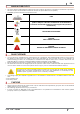
1 EN MANUAL SIMBOLOGY • The icons with the stylized figures indicates whom the subject dealt in the paragraph is addressed to (between the User and/or the Authorized Technician and/or the Specialized Stove-repairer). • WARNING symbols indicates an important note.
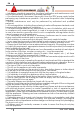
EN 4 SAFETY REQUIREMENTS • Installation, electrical connection, functional verification and maintenance must only be performed by qualified or authorised personnel. • Live electrical parts: disconnect the product from the 230V power supply before performing any maintenance operation. Only power the product after completing assembly. • Special maintenance must only be performed by authorised and qualified personnel.
EN • During its running, the stove reaches high temperatures: keep away childreen and animals and for your safety please use appropriate fireproof devices, such as heatprotecting gloves. • If the auger is blocked by a foreign object (for example: nails), and if it needs to be cleaned, do not remove the hand rejector and do not touch the auger. Please contact the Technical Assistance service. • The hand rejector can be removed exclusively by an authorized technician.
EN • Variations in colour of the painted or ceramic/serpentine parts and craquelure ceramics as they are natural characteristics of the material and product use. • Masonry work. • Plant parts (if present) not supplied by the manufacturer. Any technical interventions on the product to eliminate the above-said defects and consequent damages must be agreed upon with the Technical Assistance Centre, who reserves the right to accept the relative appointment or not.
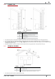
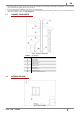
EN 9.2 CHIMNEY FLUE Fig. 1 - Chimney Flues LEGEND 1 2 3 4 5 Fig. 1 page 7 Chimney flue with insulated stainless-steel pipes Chimney flue on the existing chimney Inspection plug Inspection door ≥ 3,5 mt • The chimney flue or chimney is of great importance for the correct running of the heating appliance. • It is fundamental that the chimney flue is perfectly built and always maintained with a perfect efficiency. • The chimney flue must be sole (see Fig.
EN • It must have a vertical run without narrowing. It must be realized with fume and condensation resistant materials with thermal insulation and able to last against usual mechanical stresses. It must be insulated to avoid condensation and to reduce fume cooling effects. • The stove must be spaced out from fuels or flammable materials with an air gap or with insulating materials. Check the distance with the chimney manufacturer.
EN • The hole width for fumes exhaust must be the double of the chimney flue width and fitted in a way that the fume exhaust is assured also in case of wind. • It should prevent the infiltration of rain, snow and animals. • The outlet height in the atmosphere must be away from the reflux area caused by the roof structure or by obstacles laying nearby (see Fig. 2 page 7). 9.7 CHIMNEY COMPONENTS Fig. 5 - Chimney components LEGEND 1 2 3 4 5 6 7 8 9 10 9.8 Fig.
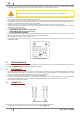
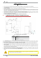
EN LEGEND 1 2 Fig. 6 page 9 Room to ventilate External air inlet • The room must be endowed with an external air recycling for a good climate in your ambient. • The air inflow from outside to the inner occurs directly, through an opening on the external wall of the room (see Fig. 6 page 9). • Bedrooms, garages, and store of flammable materials are excluded.
EN In some countries and/or regions the installation with sealed-chamber is obligatory: in case of doubt, please follow the most restrictive regulations. How to connect to the stove in the sealed chamber with concentric system: Fig. 8 - Phase1 Fig. 9 - Phase 2 Fig. 10 - Phase 3 • Original position with completely embedded tube (see Fig. 8 page 11). • Pull out the tube for 2 cm (see Fig. 9 page 11). • Insert the female tube ø 6 cm (see Fig. 10 page 11). 9.
EN 9.11 EXAMPLES OF CORRECT INSTALLATION Fig. 11 - Example 1 LEGEND 1 2 3 4 Fig. 11 page 12 Insulating material Reduction from Ø100 to Ø80 mm Inspection plug Minimum safety distance = 0,5 mt • Chimney flue installation Ø100/120 mm with an enlarged drilling for pipe transit. Fig. 12 - Example 2 LEGEND 1 2 3 4 5 6 Fig.
EN Fig. 13 - Example 3 LEGEND 1 2 3 Fig. 13 page 13 Insulating material Inspection plug Minimum safety distance = 0,5 mt • External chimney flue entirely made up of insulated stainless steel pipes, i.e. with double wall of minimum Ø100/120 mm: all must be firmly attached to the wall. For chimney against wind effects please (see Fig. 4 page 8). • Ducting system through T-unions which enables an easy cleaning without disassembling the pipes.
EN 11 INSTALLATION 11.1 INTRODUCTION • The assembly position must be chosen depending on environment, outlet, chimney flue. • Check with local authorities if there are any restrictive regulations which regard the combustible air inlet, room ventilation, fume exhaust system together with chimney flue and chimney pot. • Check if there is the combustible air inlet. • Check the probable presence of other stoves or appliances which could depress the room.
EN 11.3 GENERAL INSTALLATION WITH PEDESTAL Fig. 15 - General installation with pedestal LEGEND 1 2 3 4 Fig. 15 page 15 Stove Minimum lateral distance = 300 mm Minimum rear distance = 200 mm Minimum front distance = 1000 mm • It is obligatory to install the stove away from walls and/or pieces of furniture, with a minimum air flow of 300 mm on the sides and 200 mm on the back, to enable an eficient appliance cooling and a good distribution of heat in the room (see Fig. 15 page 15).
EN LEGEND 1 2 3 Fig. 18 page 15 Stove Minimum lateral distance = 300 mm Minimum front distance = 1000 mm • It is obligatory to install the stove away from walls and/or pieces of furniture, with a minimum air flow of 300 mm on the sides to enable an eficient appliance cooling and a good distribution of heat in the room (see Fig. 18 page 15). • For safety fire regulations the distances from flammable or sensible to heat objects (sofas, pieces of furniture, wooden covering, etc...
EN • To fix the rear support to the wall with metal plugs su1itable for the weight of the stove (see Fig. 20 page 16). 11.6 ELECTRIC CONNECTION Warning: the appliance must be installed by an authorized technician! • The electric connection occurs through a cable with plug put in an electric socket which is able to support charge and tension specific of every model, as described in the technical datas table (see FEATURES page 35). • The plug must be easily accessible when the appliance is installed.
EN Fig. 22 - Do not cover air slits 12 USE 12.1 INTRODUCTION To have the best performance with the lowest consumption please follow the here descripted instructions. • The lightning of the pellets occurs very easily if the installation is correct and if the chimney flue is efficient. • Switch on the stove at Power 1 for at least 2 hours in order to enable the materials which make up the boiler and the fireplace to adjust the inner springing stress.
EN PANEL ELEMENT DESCRIPTION Ignition plug: active ignition. Auger: active. Fume fan: active. Exchanger fan: active. - Alarm: active. Fig. 23 - LCD control display LEGEND 1 2 3 4 5 12.3 Fig. 23 page 19 Time Power State Message Temperature USER MENU By once pressing P3 key you can hace access to user parameter controlling. To let them slide press P5 and P6 keys. They are: POS. REFERENCE DESCRIPTION 1 SET CLOCK Set date and time.
EN POS. REFERENCE DESCRIPTION 5 BUZZER MODE (audio alarm) Press once P3 key and with P1 and P2 keys put in "OFF" or "ON". 6 INITIAL LOAD When the stove has its first ignition, the auger is completely empty. If it should be necessary do a precharge by pressing P3 key, then P1 key for starting up and P4 key for stop. 7 STOVE STATE It shows all parameters connected to the stove state: this is a menu for the Authorized Techinician 8 TECHNICA SETTING Only for the Authorized Technician.
EN 12.7 POWER FAILURE • After a black-out lower than 5 seconds, the stove turns back to the power which was settled. • After a black-out of more than 5 seconds, the stove enters the "COOLING WAIT" phase. Completed this phase, it starts automatically up with the different phases (see START UP page 20). 12.8 TEMPERATURE SETTING • To modify the ambient temperature it is sufficient to press P1 and P2 keys according to the desired temperature inside the menu "SET TEMP ROOM".
EN • Press P5: the display shows "SUNDAY PROG-1", with P1 and P2 keys set "ON" or "OFF". • Now press P5 and repeat all the previous instructions for Prog-2, Prog-3, Prog-4. • To exit press three times P4. 12.15 PELLET SUPPLY Fig. 24 - Wrong opening of the pellets bag Fig. 25 - Right opening of the pellets bag It is necessary to avoid to fill the hopper with the pellet when the stove is running. • Do not get the bag of pellet in contact with hot stove surfaces.
EN 13 SAFETY SYSTEM 13.1 INTRODUCTION Safety devices are used to prevent and avoid the risk of damages to people, animales and objects. It is forbidden to execute repearing by no authorized personnel otherwise the warranty and the manufacturer liability fall. 13.2 "BLACK OUT" ALARM "ACTIVE ALARM" "AL 1 - BLACK OUT": current breaking during ignition. • Reset the error with P4 key.
EN • Reset the error with P4 key. The stove carries out the phase "FINAL CLEANING" and then is in "OFF". • Check the type of glitch as ALARMS page 29. • Clean the burning pot and start the stove up again with P4 key. 14 MAINTEINANCE 14.1 INTRODUCTION For a long working life of the stove, have a periodic cleaning of the stove as described in the following paragrafs.
EN Fig. 30 page 24 and Fig. 31 page 24). • Clean also the hole for pellet drop with a brush (see Fig. 32 page 24). • The ash remains must be poured in a metal container with a sealed lid and this container must never get in touch with combustible materials (for example put on a wooden floor), as the inner ash keeps the embers firing for a long time. • Only when the embers are off the ash coul be poured in the organic waste.
EN 14.5 FUME CONDUIT CLEANING The exhaust system must be cleaned every month. Fig. 36 - Fume conduit cleaning • Remove the inspection lid of the T-union (see Fig. 36 page 26). • Extract the ash which has accumulated in the inner. • After cleaning repeat the operation in reverse order, checking the condition and efficiency of the gasket, and if necessary replace it. Is it important to hermetically seal the cap to avoid harmful fumes escaping into the room. 14.
EN Fig. 40 - Room fan cleaning • Remove the lower panel and clean with a vacuum cleaner the ash and the dust which has accumulated on the inner (see Fig. 40 page 27). 14.8 FUME PASSAGES CLEANING Clean the fume passages every year. Fig. 41 - Remove upper grid Fig. 42 - Remove top cover • Remove upper grid (see Fig. 41 page 27). • Loosen the screws of top cover (see Fig. 42 page 27). Fig. 43 - Fume passages cleaning Fig.
EN of the safety of the appliance. This operation must be executed at least once a year. 14.10 GENERAL CLEANING For cleaning external and inner parts of the stove do not use steel wools, muriatic acid or other corrosive and abrasive materials. 14.11 CLEANING OF PAINTED METAL PANELS To clean painted metal panels use a soft cloth. Do not use degreasant agents like alcool, diluents, acetone, gasoline because these could irremediably damage the varnish. 14.
EN 15 IN CASE OF ANOMALY 15.1 ALARMS Before of every intervention of the Authorized Technician, the same Technician has the duty to check that the parameters of the mother board correspond with those of the table you own. In case of doubts regarding the use of the stove, please call ALWAYS the Authorized Technician in order to avoid irreparable damages! ALARM CAUSE SOLUTION AL 1 - BLACK OUT Power cut during ignition phase. Clean the burning pot and switch the stove on again.
EN ALARM CAUSE SOLUTION INTERVENTION Empty hopper Fill the hopper. The burning pot has not been cleaned Clean the burning pot. The ignition threshold has not been reached Clean the burning pot and switch the stove on again. Faulty ignition plug Replace the ignitor resistance. Too sever external temperature Start the stove up again. Humid pellet The pellets must be stored in a dry place. Please check it. Blocked thermal probe Replace the thermal probe.
EN ALARM AL 8 - FAILURE DEPRESS 15.2 CAUSE SOLUTION Obstructed exhaust The exhaust chimney is partially or totally obstructed. Call en expert stove-repairer who executes a check from the exhaust up to the chimney pot. Fume fan out of order The pellet can burn also thanks to the chimney flue depression without the aid of the fan. Have the fume fan immediately replaced. It can be noxious to health to let the stove running without fan. Obstructed connecting nozzle Clean the connecting nozzle.
EN PROBLEM CAUSE SOLUTION The stove is without power supply Check if the plug is connected. Burned protection fuse in the electric socket Replace the protection fuses in the electric socket (3.15A-250V). The control display Faulty control does not switch display on Pellets do not reach the combustion chamber INTERVENTION Replace the control display. Faulty flat cable Replace the flat cable. Faulty electronic board Replace the mother board. Empty hopper Full the hopper.
EN PROBLEM Flames are weak and orange coloured, pellets do not burn properly and the glass blackens The exchanger fan continues to turn even though the stove has just cooled CAUSE SOLUTION Not sufficient combustion air Check as following: probable obstructions of the combustible air inlet from the back or from the bottom of the stove; burning pot obstructed holes with too ash remains. Have the fan blades and auger cleaned. Obstructed exhaust The exhaust chimney is partially or totally obsturcted.
EN 16 TECHNICAL DATAS 16.1 REPAIR INFORMATION Now we give some instructions for the Authorized Technician to take into consideration to have access to stove mechanical components. • For fuse replacement in the electric socket which lies on the back of the stove, extract the fuses to change with the aid of a screwdriver in the shutter (see Fig. 45 page 34). Fig. 45 - Shutter with the fuse to remove Proceed as follows: • Remove all panels.
EN 16.
pellet stoves· wood stoves· wood cooking stoves thermostoves· pellet fireplace inserts CADEL srl FREEPOINT by Cadel Via Foresto Sud, 7 31025 Santa Lucia di Piave (TV) - ITALY tel. +39.0438.738669 fax +39.0438.73343 www.cadelsrl.com Partner of: Rev.