
Operating Instructions and Installation Instructions
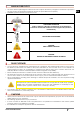
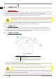
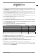
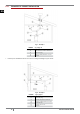
Table Of Contents
- 1 MANUAL SIMBOLOGY
- 2 DEAR CUSTOMER
- 3 CAUTIONS
- 4 WARRANTY CONDITIONS
- 5 SPARE PARTS
- 6 WARNINGS FOR THE CORRECT DISPOSAL OF THE PRODUCT
- 7 PACKAGING AND HANDLING  
- 8 CHIMNEY FLUE 
- 9 FUEL 
- 10 INSTALLATION 
- 11 USE 
- 12 MAINTEINANCE   
- 12.1 INTRODUCTION
- 12.2 BURNING POT AND ASH TRAY CLEANING 
- 12.3 FUME PIPES ANNUAL CLEANING 
- 12.4 GENERAL CLEANING 
- 12.5 CLEANING OF PAINTED METAL PANELS 
- 12.6 CLEANING OF CERAMIC PANELS 
- 12.7 GLASS CLEANING 
- 12.8 OVEN CLEANING 
- 12.9 COOKTOP CLEANING 
- 12.10 FUME PASSAGES CLEANING 
- 12.11 FANS CLEANING 
- 12.12 FAN REPLACEMENT 
- 12.13 SWITCH REPLACEMENT 
- 12.14 GASKET REPLACEMENT 
- 12.15 OVEN LIGHT REPLACEMENT 
- 12.16 HEART BREAK
- 13 IN CASE OF ANOMALY 
- 14 TECHNICAL DATAS 
- 1 IN DE HANDLEIDING GEBRUIKTE SYMBOLEN
- 2 BESTE KLANT
- 3 WAARSCHUWINGEN
- 4 GARANTIEVOORWAARDEN
- 5 RESERVEONDERDELEN
- 6 AANWIJZINGEN VOOR EEN CORRECTE VERWIJDERING VAN HET PRODUCT
- 7 VERPAKKING EN VERPLAATSING  
- 8 ROOKKANAAL 
- 9 BRANDSTOF 
- 10 INSTALLATIE 
- 11 GEBRUIK 
- 12 ONDERHOUD   
- 12.1 INLEIDING
- 12.2 REINIGING VUURPOT EN ASLADE 
- 12.3 JAARLIJKSE REINIGING VAN DE ROOKGASSENLEIDINGEN 
- 12.4 ALGEMENE REINIGING 
- 12.5 REINIGING VAN GELAKTE METALEN ONDERDELEN 
- 12.6 REINIGING VAN DE MAJOLICA ONDERDELEN 
- 12.7 REINIGING VAN HET GLAS 
- 12.8 REINIGING OVEN 
- 12.9 REINIGING KOOKFORNUIS 
- 12.10 REINIGING BINNENKANT OVEN 
- 12.11 REINIGING VENTILATOR 
- 12.12 VERVANGING VENTILATOR 
- 12.13 VERVANGING SCHAKELAAR 
- 12.14 VERVANGING VAN DE PAKKINGEN 
- 12.15 VERVANGING OVENLAMP 
- 12.16 DEFECT VUURPOT 
- 13 IN GEVAL VAN ONGEMAKKEN 
- 14 TECHNISCHE GEGEVENS 

9
WOOD COOKING STOVES
EN
LEGEND Fig. 6 page 8|Fig. 7 page 8
1 Room to ventilate
2 Adjacent room
3 External air inlet
4 Cleft under the door
• The room must be endowed with an external air recycling for a good climate in your ambient.
• The air inow from outside to the inner occurs directly, through an opening on the external wall of the room
(see Fig. 6 page 8); otherwise it occurs indirectly by air suction from rooms adjacent to the one to ventilate
(see Fig. 7 page 8).
• Bedrooms, garages, and store of ammable materials are excluded.
• The air inlet should have a total net surface of 100 sqcm
2
: the aforesaid surface is to widen if inside the room
there are other activated appliances (for example: electric ventilators for foul air suction, cooker hoods, other
stoves, etc...) which depress the environment.
• At switched on appliance it is necessary to check that the pressure fall between the room and the outside
does not exceed 4,0 Pa value: if necessary widen the air inlet (EN 13384).
• The air inlet must be realized at a height close to the oor with an external grid against birds. In such a way it
cannot be obstructed by any object.
• In case of installation with sealed-chamber the air inlet is not necessary.
8.9 CHIMNEY FLUE CONNECTION
Your stove works through a natural draught. It is obligatory to check that all pipes are realized in compliance
with the following regulation on material selection: EN 1856-1, EN 1856-2 e UNI/TS 11278. All must be effected by
specialized personnel or companies as provided by UNI 10683:2012.
• The connection between the appliance and the chimney ue should be short in order to favor the draught
and to avoid condensation in the pipes.
• The fume conduit should be equivalent or longer than the outlet joint ones.
• Some stove models are endowed with a lateral and/or back exhaust. Check that the unused exhaust is
sealed with the plug given with standard equipment.
SYSTEM TYPE Ø150 mm PIPE Ø240 mm PIPE
Minimum vertical length 1,5 mt 2 mt
Maximum length (with 1 union) 6,5 mt 10 mt
Maximum length (with 3 unions) 4,5 mt 8 mt
Maximum number of unions 3 3
Level section (minimum inclination 3%) 2 mt 2 mt
Installation at a height above 1200 m a.s.l. NO Obligatory
• Use a specic plate pipe for stoves.
• It is forbidden to use metal, bre cement or aluminium exible pipes.
• For change of direction it is obligatory always to use a T-union (or a curve not with right angle) with inspection
plug which enables an easy periodic cleaning of the pipes.
• Please assure you that after the cleaning the inspection plugs are sealed with its efcient gasket.
• It is forbidden to connect more appliances to the same fume conduit.
• It is forbidden to convey in the same fume conduit exhausts from overhanging cooker hoods.
• It is forbidden to exhaust ue gases directly from the wall towards the outside and closed spaces also at open
top.
• It is forbidden to connect any other appliance (wood stoves, cooker hoods, boilers, etc...).
• The fume conduit must be placed at a distance of minimum 500 mm from ammable or heat-susceptible
components.
• The fume conduit must be connected with stove exhaust in a xed and tight manner, and if required with the
insertion of a damper (see FEATURES page 27).