
User Guide


Example—Creating Symbols from Scratch
221
3 From the Graphics menu, select Draw Text to place the
labels D1 through D4 on the diode symbols.
4 To change the size of the text, double-click the text and
adjust the size.
The number is a percentage relative to the usual size.
5 From the Graphics menu, select Box and click once to
attach the bounding box to the cursor.
a Move the cursor to the lower right so that the
bounding box encloses the entire symbol.
b Click again to freeze the box; all pin connection
points must lay on, or inside of, the boundary box.
The boundary box defines the area of the symbol
in PSpice Schematics.
6 From the Graphics menu, select Origin and click to
attach the origin to the cursor.
a Move it into position.
b Click again to drop it.
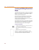
Setting the Attributes
The last step in creating a symbol is to set up the attributes
so the symbol can be used for simulation.
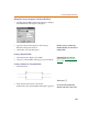
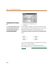
1 From the Part menu, select Attributes to display the
following attributes in the Attributes dialog box:
REFDES
PART
MODEL
TEMPLATE
a Click REDES and set its value to:
U?
This is the reference designator that appears in
your schematic and in the netlist.
b Click Save Attr.
I
f
you c
l
ic
k
anyw
h
ere wit
h
in t
h
e area o
f
t
h
e
boundary box in PSpice Schematics, the
symbol will be selected.
Th
e origin is t
h
e point t
h
e sym
b
o
l
wi
ll
rotate
around when in PSpice Schematics. Usually
it is on the hot spot of the top left pin, but
it is not required.
You can a
l
so set it to: BRIDGE?