M7000
TABLE OF CONTENTS INTRODUCTION 1 FEATURES 2-4 INSTALLATION BASICS 4 -8 INSTALLATION WIRING 9 -12 VARIOUS IMPEDANCE WIRING 13 -14 SPECIFICATION 15
Thank you for purchasing a Cadence Amadeus Amplifier. The Amadeus series is a breakthrough in sound quality and design. The amplifier features our own hybrid digital technology that was made famous with the venerable A7HC--only we took it one step further. Not only is the Amadeus a Digital Class D amplifier it is also capable of playing the full range audio spectrum. (All models except the M7000 which is a pure sub woofer amplifier.
NICKEL PLATED TERMINALS All the terminals on the amplifier are solid brass and satin nickel plated for high conductivity and minimum impedance loss. The power and ground terminals are extra large and capable of accepting 4 gauge wire. The speaker terminals can accept 8 gauge wire. When wiring the amplifier, be sure to strip just enough wire that fits into the terminal so that bare wires do not touch each other, or the amplifier chassis and cause a short circuit.
BASS DRIVE EQUALIZATION CIRCUITRY A narrow "Q" shelving equalization circuit is included in the amplifiers. The equalization system is preset at 45Hz. The boost control allows you to add up to 12dB of Bass Drive effect. Utilize the Bass Drive to tailor your bass response to your systems needs. Please keep in mind that by adding Bass Drive you are adding stress on your speakers.
Thermal Protection: When the amplifier reaches an unsafe operating temperature of 80 degrees Celsius the amplifier will turn off. Once the amplifier cools down, simply reset the amplifier by its Remote connection,(turn the amplifier off and then of again once you have given the amplifier a chance to cool down) and the amp will once again begin to play.
It is recommend that you layout your sound system design on paper first. This will help you during the installation so that you will have a wiring flow chart and not miss-wire any of your components. Mount the amplifier in the trunk or hatch area of your vehicle. Never install an amplifier in the engine compartment or on the firewall. Please be sure to leave breathing room around the amplifier heatsink so that it can dissipate the heat it produces efficiently.
Over the years we have received many an amp back to our service department with melted power/ground terminals. The cause of this is a bad ground connection. When there is a lack of good ground heat builds up at the weakest point which is the contact screw of the terminal. Over time the heat generated will begin to melt the terminal. It is a good practice to feel the power and ground wires with your hands, near their amplifier connection after having played the amp for a while.
ADJUSTING THE SYSTEM Once the system is operational, the first thing to do, is set all crossover points to approximate settings. In the case of the basic subwoofer system, set the Low Pass filter crossover at 100 Hz or so. Set the Bass Boost equalizer control to 0 dB. Now you should set the amplifiers LEVEL adjustment. The knob accessible on the front of the amplifier marked Input Level adjusts the input sensitivity from150mV to 9 Volts.
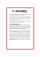
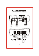
PROTECTION LINE OUT LOW INPUT LEVEL SUB SONIC LOW PASS BASS BOOST PHASE SHIFT POWER SPEAKER L Min Max 15 40Hz 50 150Hz 0 180 0 +18dB BRIDGED MODE R MASTER LINE OUT to SUB amp LINE IN SLAVE DATA LINK Woofer From OUTPUTS of HEAD UNIT REMOTE POWER FUSES +12V REM Remote Control GROUND To REMOTE TURN-ON from HEAD UNIT In-Line Fuse Holder BATTERY GND Distribution Block Capacitor 8
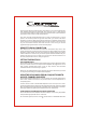
PROTECTION LINE OUT LOW INPUT LEVEL SUB SONIC LOW PASS BASS BOOST PHASE SHIFT POWER SPEAKER L Min Max 15 40Hz 50 150Hz 0 180 0 +18dB BRIDGED MODE R SLAVE DATA LINK 。「 MASTER BRIDGED MODE LINE OUT to SUB amp LINE IN From OUTPUTS of HEAD UNIT MASTER SLAVE SPEAKER IMPEDANCE 2 OHMS! BRIDGED SWITCH: MASTER POSITION PROTECTION LINE OUT LOW INPUT LEVEL SUB SONIC LOW PASS BASS BOOST PHASE SHIFT POWER SPEAKER L Max 15 INPUT SENSITIVITY R 2-8V 100mV-2V 40Hz 50 150Hz 0 180 0
HOW TO TROUBLE SHOOT A SYSTEM GENERAL A car stereo system consists of many different pieces of equipment connected together, and a logical process of elimination will find the problem area, by isolating sections, and checking them one at a time. Before following the instructions below, check and double check all wiring and connections.
AMPLIFIER OVERHEATING AND SHUTTING DOWN The most common cause for this problem is when amplifiers are overloaded with speaker impedances lower than what they are rated for. Double-check the impedance of your speakers and their wiring. Also check that no speaker leads are shorted to the vehicle metal chassis. AMPLIFIER GOING INTO PROTECTION When an amplifier goes into protection mode, we have to first establish whether the problem lies with the amplifier, or whether it is something in the installation.
M7000 4 Ohm Competition rating 50 Watts 2 Ohm Power 500 Watts 1 Ohm Power 1000 Watts Variable Low Pass Filter 50Hz - 150Hz Variable Sub Sonic Filter 15Hz - 40Hz Phase Shift Control Frequency Response Signal/Noise Ratio Damping Factor Minimum THD Input Voltage Dimensions(L x W x H) 0 - 180 15Hz - 150KHz >100dB >500@100Hz <0.03% 200mV - 9 Volt 12.5" x 7.25" x 2.6" 2 Ohm Power when two M7000 are strapped together is 2000 Watts.
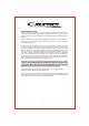
4 X DUAL VC 8 OHM SPEAKER WITH SERIES VOICE COILS, ALL IN PARALLEL 2 OHM TO AMPLIFIER 4+4 OHM 4+4 OHM PARALLEL: SINGLE VOICE COIL SPEAKERS 2 OHM TO AMPLIFIER 4 OHM 4 OHM SERIES: SINGLE VOICE COIL SPEAKERS 2 OHM 4 OHM TO AMPLIFIER 2 OHM 13 4+4 OHM 4+4 OHM
PARALLEL: DUAL VOICE COIL SPEAKERS SERIES: DUAL VOICE COIL SPEAKERS 8 OHM TO AMPLIFIER 4+4 OHM 2 OHM TO AMPLIFIER 4+4 OHM 2X DUAL VC 2 OHM SPEAKERS WITH SERIES VOICE COILS, ALL IN PARALLEL 4 OHM TO AMPLIFIER 2+2 OHM 2 OHM TO AMPLIFIER 2 OHM TO AMPLIFIER 2+2 OHM 2+2 OHM 1+1 OHM Please note that the minimum impedance load for single Cadence Amadeus Series amplifiers is 2 ohm stereo and 4 ohm mono bridged. Lower impedance loads will cause overheating and may damage the amplifiers.