
Installation Sheet

6
INSTALLATION INSTRUCTIONS
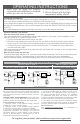
Figure 10
this set of
wires from
the circuit
breaker
additional copper wire added here
to grounding screw
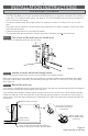
MULTIPLE HEATERS ON ONE CIRCUIT BREAKER (240 OR 208 VOLTS ONLY)
1. Route the electrical supply wire from the circuit breaker to heater #1. Remove two knockouts and
attach two sets of electrical supply wire with two cable clamp connectors (not included) leaving a
minimum of 6 inches wire lead—one set from the circuit breaker, the other set to heater #2 (See
Figure 8).
2. The two supply ground wires in the wall can of heater #1 need to make a 3-wire connection with the
grounding screw. Attach a short copper ground wire to the grounding screw in the wall can. Connect
this wire and the two supply ground wires with a wire connector (not included) (See Figure 8).
3. For heater #1, connect each heater wire with one of the supply wires going to the circuit breaker,
and one of the supply wires going to heater #2. Each of the wires from heater #1 must have a 3-wire
connection. For heater #2, make the connections in the wall can as shown below.
More than one heater can be wired in parallel on the same circuit breaker (be sure to check national
and local codes for safety requirements). Additional electrical supply wire and cable clamp connectors
are required. The heaters must be in the same room.
Maximum amperage you can put on one circuit breaker is limited to 80% of the circuit breaker capacity.
this set of wires
from heater #1
heater #1
(back)
heater #2
(back)
this set of wires
to heater #2
After making all connections, proceed with STEP 4 Wire connections, number 2 above.
Install grill
STEP 5
Attach grill with screws provided. Slide knobs onto shafts; timer on left and thermostat on right. Turn
electrical power back on at the main disconnect panel.
Proceed to OPERATING INSTRUCTIONS.
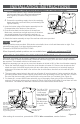
4. Attach the heater assembly at top of the wall can with screw provided.
120 Volt Figure 9
For 120 volts (CB103T only), connect the neutral
(white) supply wire to the black and white striped
wire (Figure 9).This wire is only on CB103T
models.
C. Connect the remaining supply wire to the remaining
heater wire with a wire connector (not included) (See
Figures 8 and 9).
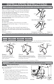
2. Insert the bottom edge of the heater assembly into the
D-shaped tabs at the bottom of the wall can.
3. Push all wires back into the bottom of the wall can.
Make sure connections are tight and none of the wires
are caught between the motor and the wall can, or
pinched between the side of the heater and the wall can.
INSERT THE HEATER ASSEMBLY IN THE WALL CAN
More frequently asked questions on our website here: cadetheat.com/support/FAQ
wall can
A
B
C
For 240 or 208
volts pictured,
both supply
wires (black and
white) are hot.
Wrap supply
(white) wires
with black tape
to identify them
as hot.