
Owner's Manual

INSTALLATION INSTRUCTIONS
6
L2
Ground
L1
Ground
L1
L2
Ground
L1
L2
Neutral
Ground
L1
Ground
Neutral
L1
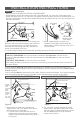
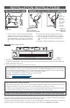
Figure 9
Figure 11
Figure 12
Double pole
wall thermostat
left end wiring
120 volt left
end wiring
240/208 volt
left end wiring
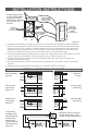
INTERNAL HEATER WIRING DIAGRAMS
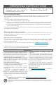
Connecting
multiple units
240 or 208 volt
models only
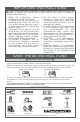
Multiple heaters must join
at wall thermostat, not in
heater wiring compartment
1. A separate set of electrical supply wire must be run from the wall thermostat to each baseboard.
2. All the 3-wire connections must be made in the electrical junction box of the wall thermostat (See
Figures 8 and 12)! They cannot be made in either of the wiring compartments of the heaters. An
extra deep electrical junction box is recommended so you’ll have enough room for all the wires.
Tuck all wires back into the junction box and make sure the connections are tight.
3. In the wiring compartment of each heater, connect one supply wire to one of the heater wires with
a wire connector (not included), it doesn’t matter which one (See Figure 2 or 4).
4. Connect the remaining supply wire to the remaining heater wire with a wire connector (not
included) (See Figure 2 or 4).
5. Tuck all the wires back into the individual wiring compartments, and make sure the connections
are tight.
6. Screw the wiring compartment covers back on. Proceed to STEP 3 on page 5.
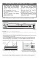
from power
supply
double
pole wall
thermostat
(sold
separately)
Figure 8
ground
wire
connection
connections
with power
supply (line)
connections
with heaters
(load)
to
heater
#1
to
heater
#2
If both supply wires
are hot, wrap (white)
supply wires with
black tape to identify
them as hot, not
neutral!
L2/Neutral
Ground
L1
Ground
L2/Neutral
L1
Figure 10
208 volt left
end wiring
L2
Ground
L1
Ground
L1
L2
Neutral
Ground
L1
Ground
Neutral
L1
L2/Neutral
Ground
L1
Ground
L2/Neutral
L1
120 volt right
end wiring
240/208 volt
right end
wiring
208 volt right
end wiring