
Installation Sheet

INSTALLATION INSTRUCTIONS
5
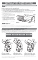
INSERT THE HEATER ASSEMBLY IN THE WALL CAN
Wire connections
STEP 4
Install grill
STEP 5
Attach grill with the screws provided.
tip: hand tighten both screws first before securing. The open part of the grill goes on the bottom.
Turn power on at the main disconnect panel. Proceed to OPERATING INSTRUCTIONS.
Figure 4
Figure 3
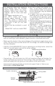
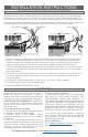
Wire Connections
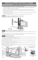
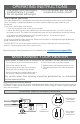
HOW TO CHANGE THE WATTAGE
Your heater has two connection wires and the wall can has a green grounding wire. Your supply wire
has two connection wires and a supply ground wire.
1. Connect supply ground wire to green grounding wire in wall can (See Figure 3).
2. Connect one of the supply wires to one of your heater wires with a wire connector (not included):
A. for 240 volts, it doesn’t matter which heater wire (Figure 3);
B. for 120 volts, connect the neutral (white) supply wire to the white heater wire (Figure 3).
3. Connect the remaining supply wire to the remaining heater wire with a wire connector (not
included) (See Figure 3).
4. Insert the bottom edge of the heater
assembly into the bottom of the wall
can (See Figure 3).
5. Push all wires back into the side of
the wall can. Make sure connections
are tight and none of the wires are
caught between the heater assembly
and the wall can.
6. Attach the heater assembly at top of
the wall can with screw provided.
Multi-watt RM models oer a variety of heat output options. They are factory set to maximum wattage
(Figure 4). If you have a multi-watt model, you can change the heating element wire connections to a
lower wattage on the right hand side of the heater assembly (See Figures 5 and 6).
If you change the wattage, mark the wiring diagram on the back of the heater with the wattage used
for future reference. Proceed to STEP 4.
Multi-watt models RM162, RM168 and RM151 only
Figure 5 Figure 6
supply
wires
green grounding wire
wall can
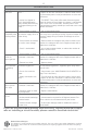
Model
Maximum Wattage
Figure 4
Medium Wattage
Figure 5
Lowest Wattage
Figure 6
RM162, RM168 1600 900 700
RM151 1500 1000 500
blue
terminal
remove blue terminal and
wrap end with electrical
tape; secure to other wires
with zip tie.
yellow
terminal
yellow
terminal
remove blue terminal and wrap
end with electrical tape; secure
to other wires with zip tie. Move
yellow terminal and attach it where
blue terminal was removed.
yellow
terminal
moved
here
blue
terminal
removed
tip: to remove terminals
easier, pull and wiggle
slightly back and forth at the
same time
blue terminal
removed