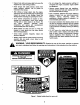
| [l Aiw e L OPERATOR’S MANUAL Automatic Transmission Lawn Tractor Models 1600 1800 IMPORTANT: READ SAFETY RULES AND INSTRUCTIONS CAREFULLY Damning: This unit is equipped with an internal combustion engine and should not ba sad on or near any unimproved forest covered, brush-covered or grass-covered land unless the engine's exhaust system is equipped with a spark arrested meeting applicable local or state laws (ff any).
SECTION 1: TABLE OF CONTENTS FINDING YOUR MODEL NUMBER . CALLING WARRANTY SERVICE .. IMPORTANT SAFE OPERATION PRACTICES. SAFETY LABELS FOUND ON YOUR UNIT. SLOPE GAUGE ATTACHMENTS & ACCESSORIES. TRACTOR CONTROLS .. OPERATION. . n ADJUSTMENTS 14 MAINTENANCE 17 LUBRICATION . 23 TROUBLESHOOTING GUIDE . WARRANT INFORMATION SECTION 2: FINDING YOUR MODEL NUMBER This Operator's Manual is an important part of your new rider. It will help you assemble, prepare and maintain your rider.
SECTION 4: IMPORTANT SAFE OPERATION PRACTICES WARNING: THIS SYMBOL POINTS QUT IMPORTANT SAFETY INSTRUCTIONS WHICH, IF NOT FOLLOWED, COULD ENDANGER THE PERSONAL SAFETY AND/OR PROPERTY OF YOURSELF AND OTHERS. READ AND FOLLOW ALL INSTRUCTIONS IN THIS MANUAL BEFORE ATTEMPTING TO OPERATE YOUR LAWN MOWER. FAILURE TO COMPLY WITH THESE INSTRUCTIONS MAY RESULT IN PERSONAL INJURY. WHEN YOU SEE THIS SYMBOL, HEED ITS WARNING.
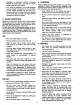
. Disengage all attachment clutches, thoroughly depress the brake pedal, and shift into neutral before attempting to start engine. Your mower is designed to cut normal residential grass of a height no more than 10%, Do not attempt to mow through unusually tall, dry grass pasture) or piles of dry leaves. Debris may bulls up on the mower deck or contact the engine exhaust presenting a potential fire hazard. 2.
« Keep all nuts, bolts and screws tight to be sure the equipment is in safe working condition. « Never damper with safety devices. Check their proper operation regular. Use all guards as instructed in this manual. * After striking a foreign object, stop the engine, remove the wire from the spark plug and thoroughly inspect the mower for any damage. Repair the damage before restarting and operating the mower.
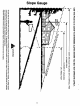
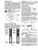
Slope Gauge USE THIS PAGE AS A GUIDE TO DETERMINE SLOPES WHERE YOU MAY NOT OPERATE SAFELY. < SIGHT AND HOLD THIS LEVEL WITH A VERTICAL TREE I OVERPOWER s I l@—— ACORNEROFABUILDING -~ FENCE POST MC OZD ' 1 e reported l,wlmzdeaw — = “eased 50 ~ I ~
SECTION 5: ATTACHMENTS & ACCESSORIES MODEL NUMBER | DESCRIPTION UM-1806-601 Attachments Twin Nagger Grass Collector (For 42-inch Decks Only) UM-180-602 Attachments Twin Nagger Grass Collector {For 46-inch Decks Only) UM-180-112 Mulch Kit {For 42-inch Decks Only) UM-180-118 Mulch Kit {For 46-inch Decks Only} UM-130-603 Attachments Front Bumper Kit UM-180-504 ‘Trachea Storage Container (mounts on rear of tractor} FEM-180-822 Fast Attach 46-inch Front Dover Blade UM-150-823 42-inch Two-stage Snow Throws NOTE:
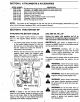
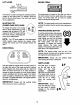
SECTION 7: CONTROLS wfiv omm 7N6TE: Storing Wheel not shown for clarity Figure 3 A Ignition Switch H Brake Peal B Throttle Control Lever | Parking Brake Button C Choke Control (it so equipped) J Shift Lever D Indicator Monitor/Hour Meter K Seat Adjustment Lever E Lift Lever L Cup Holder F PTO (Power Take-off) Knob M Cruise Control Button G Drive Pedal NOTE: Any reference in this manual to the RIGHT or LEFT side of the tractor is observed from operator's position.
IGNITION SWITCH To-start the engine, insert key into the ignition switch and tum clockwise to the START position. Release key to the ON position once engine has fired. See Figures 4. Refer to STARTING THE ENGINE in the OPERATION section of this manual for detailed starting instructions. The ignition switch is also used to operate the headlights.
LIFT LEVER e My The lift lever is used to change the operating position {height} of the cutting deck. To operate, move the lever to the left, then place in the notch best suited {for your application. ELECTRIC PTO (POWER TAKE-OFF) KNOB To engage the power to the cutting deck or other attachments on units equipped with an electric PTO, pull outward on the PTO knob. Push the PTO knob inward to disengages the power 1o the attachments.
CRUISE CONTROL BUTTON The cruise control button is located on the tractor dash panel to the left of the ignition switch. Push the cruise control button while traveling forward at a desired speed. While holding the button in, release pressure from the drive pedal. This will engage the cruise control and allow the tractor to remain at that speed without applying pressure 1o the drive pedal. Depress the brake pedal or the drive peat to deactivate cruise control.
SETTING THE CUTTING HEIGHT Select the height position of the cutting deck by placing the deck [ift fever in any of the six different cutting height notches on the right side of the fender. Then adjust the deck wheels so that they are at least 1/4 inch to 1/2 inch above the ground when the tractor is on a smooth, flat surface such as a driveway. A NOTE: The deck wheels are an anti-scalp feature of the deck and are not designed to support the weight of the cutting deck.
+ While continuing to hold the cruise button in, lift your foot from the drive pedal (you should feel the cruise latch engage). » If properly engaged, the cruise control button and the drive pedal should lock in the down position, and the tractor will maintain the same forward speed, » Disengage the cruise control using one of the following methods: + Depress the brake pedal to disengage the cruise control and stop ths tractor. + Lightly depress the drive pedal.
+ The operator must remain in the tractor seat at all times. If the operator should leave the seat without pushing the PTO knob inward into the disengaged (OFF) position, the tractor's engine will shut off, IMPORTANT: The PTO knob cannot be in the engaged (ON) position when the tractor is driving in the reverse direction. The PTO knob must be in the disengaged (OFF) position when the shift lever is in REVERSE or the PTO will automatically shut off, Refer to SAFETY INTERLOCK SWITCHES in this section.
Side to Side If the cutting deck appears to be mowing unevenly, a side to side adjustment can be performed. Adjust if necessary as follows: WARNING: Turn the tractor's engine off, remove the key from the ignition switch and apply the A tractor’s parking brake before making any adjustments to the cutting deck. + With the tractor parked on a firm, level surface, place the lift [ever in the top notch (highest position) and rotate the both blades so that they are perpendicular with the tractor.
Adjust the drag links so that equal lengths are threaded into the ball joint on the left side and the bail joint on the right side: + Loosen the jam nut found on the drag link at the rear of the ball joint. See Figure 10, = Remove the hex nut and lock washer on the top of ball joint. See Figure 10. + Thread the ball joint toward the jam nut to shorten the drag link. Thread the ball joint away from the jam nut 1o lengthen the drag link.
SECTION 10: MAINTENANCE WARNING: Disconnect the spark plug A wire(s) and ground against the engine ENGINE before performing any adjustments, repairs or maintenance. Refer to the separate engine manual for engine maintenance instructions. Check engine oll level before each use as instructed in the separate engine manual packed with your unit. Read and folio Instructions carefully. Changing Engine Oil * Unscrew oil fill cap and remove dipstick from the oil fill tube. See Figure 13.
. » Grasp the PTO idler pulley bracket and pivot it Repeat the above steps on the left side of the toward the discharge chute to relive tension tractor. on the belt. Remove the deck belt from around Move the lift lever into the notch on the the electric PTO clutch and the PTO idler right fender to raise the deck lift arms out of pulley. the way.
* Route the new belt as shown in Figure 14, around the deck pulleys, idler pulley and electric PTO clutch. « Remount the belt guards removed earlier. Electric PTO PTO Tidier Pulley " beck belt (Bottom) {mounted on tractor) B PO bet (Top) Deck idler Pulley Right Hand Double Pulley (beneath belt guard) Left Hand Double Pulley Center Pulley Set-Tapping Screws NOTE: Left hand bet cover not shown for clarity.
. Drive bet (Lower) I rive bet (upper) Variable-speed Tulle Shift Lever Errs Idler Pulley Engine Pulley airmen TR T e Single-speed- Transmission Transmission Pulley NOTE: View shown from above tractor. Front of Tractor » Figure 16 Upper Drive Belt * Locate the transmission idler pulley on the upper drive belt by looking through the battery tray opening. See Figure 16. + Grasp the bracket and pivot the transmission idler pulley toward the rear of the tractor to release tension on the upper drive belt.
+ Slide the belt off of the variable-speed pulley as you lift the pulley up and out through the battery tray opening. NOTE: Jacking the rear of the tractor up off the ground and securing it with jack stands at this point in the procedure will ease the following steps, but is not necessary. « Remove the rear idler pulley from the double idler bracket while routinizing the belt from around both the rear and the front idler pulley. Refer to Figure 16.
CUTTING BLADES g WARNING: Cutting blades are sharp. Always protect hands by wearing heavy leather work gloves to grasp blades. The blades may be removed for sharpening or replacement as follows. » Remove the deck from beneath the tractor, (refer to DECK REMOVAL earlier in this section for detailed instructions} then gently flip the sack over to expose its underside. * Place a block of wood between the center deck housing baffle and the cutting blade to act as a stabilizer. See Figure 20.
Charging If the unit has not been put into use for an extended pried of time, charge the battery with an automotive-type 12-volt charger for a minimum of one hour at six amps. WARNING: Batteries give off an A explosive gas during and for some time after charging. Charge battery in a well ventilated area and do net allow a spark or an open flame near the battery. TIRES The recommended operating fire pressure is approximately 10 psi for the rear tires and 14 psi for the front tires.
SECTION 12: TROUBLESHOOTING GUIDE Trouble ::zs Corrective Action Engine will |Safety switch Hers are two safety switches in the starting circuit of your unit: the brake pedal switch note rank {bunion not and the seat switch. Make certain the actuators are fully depressing the buttons on depressed. each switch. The PTO knob must be in the disengaged (OFF) position in order to start the engine, also. Battle installed | The battery must be installs with negative terminal attached to black ground wits.
Models 1600 & 1800 186 REF. PART NO. NO. DESCRIPTION 1 }625-0051 Bulb/Socket Headlight Assembly 725-1739 Bulb Only 725-1649 Socket Only 2 1628-0828 Wiring Harness 3 1626-0126 Harness Adapter, #18x5 4 [710-0599 |Self Tapping Crow, x .
Tractor Body REF, PART REF. PART NO. NO. DESCRIPTION NO. NO. DESCRIPTION 1 [683-0195 Bracket Assembly (8-style} 24 17510803 Fuse Cap 2 1710-0599 Self-tapping Screw, .5 25 |751-0659 Fuel Tank 3 7100751 Hex Cap Screw, x .62 26 |710-0808 Set-tapping Screw, x 1.25 4 710-0924 Phillips Pan Screw, x .75 27 {710-0895 Self-tapping Screw, x.756 5 7101017 Truss Phillips Screw, x 625 28 |710-8217 Truss Phillips Screw, #8-32 x .375 6 (7101268 Screw, #10-16x .375 29 {712:0142 Hex Nut, #8-32 7 |710-3008 Hex Cap Screw, x .
Lift Assembly REF. PART REF. PART NO. NO. DESCRIPTION NO. NO. DESCRIPTION 1 |847-0040 Deck Stabilizer Rod 27 [710-0260 Carnage Bolt, x .62 2 |683-0187 Lift Shaft Assembly 28 [710-0804A (Self Tapping Screw, x .625 & |711-0332 Clevis Pin, .5x .78 29 |710-0895 Self Tapping Screw, 4 [712-0206 Hox Nut, 30 Lift Aver Cover 5 1712:0431 Flange Lock Nut, 31 (7312104 Shift Lever Cover w/ Cup Holder 6 |712-3004A |Flange Lock Nut, 32 |738-0155 Shoulder Screw, .437 x 1.
Steering Assembly REF. PART REF, PART NO. NO. DESCRIPTION HNO. NO. DESCRIPTION 1 [683-0263A [Lower Frame Assembly 27 |883-0128A |Pivot Bar 2 |710-0804A EFT-tapping Crow, 16-18 % .625 28 |712-0431 Flange Lock Nut, 3 7830726 RH Pivot Support Bracket 29 [714-0470 Cotter Pin 4 |783-0727 LH Pivot Support Bracket 30 (726-0214 Push Cap, 5/8 § |783-0728 Pivot Bar Bracket 726-0341 Push Cap, 3/4 6 |710-0514 Hex Cap Screw, x 1 (Grade 5) 31 |738-0162 Flat Washer, |711-1408 LH Drag Link 82 [736-0187 Flat Washer, .
Drive System REF. PART REF. PART NO. NO. DESCRIPTION KNG, NO. DESCRIPTION 1 [17833 Shift Aver Bracket 45 |754-0467 Variable-speed Belt 2 |17840 Transient Mounting Bracket 46 |754-0468 Drive Belt 3 |618-0307 Single-speed Transmission Assembly 47 |756-0981 Flat infer, 2.75 OD 4 |631-0009 Sifter Knob 48 |783-0837 Shit Lever Support 5 |847-0041 Shift Aver 49 (783-0867A [Transmission Torque Bracket 6 |656-0048 Variable-speed Pulley Assembly 50 |783-0669 Tidier Bracket 7 |856-0051 Transmission Pulley, 8.5 x .
Power Take-off System REF. PART REF. PART NO. NO. DESCRIPTION NO. NO. DESCRIPTION 1 [712-043% Flange Lock Nut, 23 [712-3010 Hex Nut, 2 |732-0735 Compression Spring, 1.318 x 2.37 24 Hex Cap Crow, x 1,75 (Grade 5) 3 |783-0783 Spacer Cup, 1.5 0D 25 |732-0978 Extension Spring, 1.2 0D x 3.638 4 |732.0956 Compression Spring, |714-0118 Square Key, [710-0804A |Self Tapping Screw, x .625 27 |710-3025 Hex Cap Screw, x .625 6 (710-0751 Hex Cap Crow, x .
Cutting Decks REF. PART REF. PART NO. NO. DESCRIPTION NO. NO. DESCRIPTION 1 [17982 Reinforcement Spindle Plate 29 |738-0873 Shoulder Spacer, 498 x 1.53 2 |618-0240 Spindle Assembly, § Dia. 30 |742-0611 Three-in-one Blade, Star Center, 16.28 756-0959 Pulley Only 31 7420612 Th res-in-ons Blade, Star Center, 14.
Engine Accessories PART ND. DESCRIPTION 2| PO RNPRNMDNR GRBRLESRUBBRRUNNBorIsandnrpeoNonsrwn om 710-0148 Self Tapping Screw, #8-32 x 375 710-0589 Sol Tapping Screw, 5 710-0804A | Self Tapping Screw, x .625 710-1237 Screw, #10-32 x .825 710-1314 Socket Cap Screw, x .625 710-1315 Self Tapping Screw, x 1.25 712-3017 Hex Nut, BS-691613 | Exhaust Gasket (Vanguard Twin) 726-0205 Hose Clamp 736-0119 Lock Washer, 5/16 736-0148 Lock Washer, 3/8 x .882 x .
MANUFACTURER’S LIMITED WARRANTY FOR: The limited warranty set forth below is given by Cub Cadet Corp. with respect to new merchandise purchased and used in the United States, its possessions and territories. Cub Cadet Corp. warrants this product against defects in material and workmanship for a period of two (2) years commencing on the date of original purchase and will, at its option, repair or replace, free of charge, any part found to be defective in material or workmanship.