
Installation Guide


INSTALLATION INSTRUCTIONS
5
6. Screw wiring compartment cover back on.
7. Turn power back on at the main disconnect panel.
8. Proceed to OPERATING INSTRUCTIONS.
How to operate your heater
The room temperature is controlled by a line voltage thermostat located either on the wall, or on the
heater. Once installation is complete and power has been restored, follow the steps below for your
thermostat.
If you have a mechanical wall or built-in thermostat:
1. Turn the thermostat knob fully clockwise.
2. When the room reaches your comfort level, turn the thermostat knob counterclockwise
until the heater turns off. The heater will automatically cycle around this preset temperature.
3. To reduce the room temperature, turn the knob counterclockwise. To increase the room
temperature, turn the knob clockwise.
If you have an electronic wall or built-in thermostat, follow the instructions in the programming and
operating guide included with your thermostat.
PLEASE NOTE: Upon initial start-up, the heater may emit a burning odor. This is not dangerous,
and is due to a protective lubricant used during the manufacturing process. It typically dissipates
within several hours.
OPERATING INSTRUCTIONS
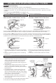
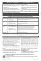
Figure 11a
Figure 10a
8F2025 ONLY / LEFT SIDE WIRING 8F2025 ONLY / RIGHT SIDE WIRING
DO NOT CUT!
Left Side of Baseboard Shown
2000 Watt Conguration / Heater is wired on right side
Left Side of Baseboard Shown
2000 Watt Conguration / Heater is wired on left side
1. Cut the factory
connection without
the red wire.
2. Connect one
supply wire to one
heater wire.
3. Connect the
remaining supply
wire to the
remaining heater
wire.
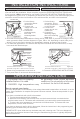
4. All model 8F2025 model baseboards are factory set for 2500 watts. If you want to change to 2000
watts, proceed to Step 5 and the diagrams in Figure 10B or 11b, depending on which side you’re
wiring. If you do not want to change your baseboard’s wattage, proceed to step 6 below.
5. For 2000 watt applications: Cut red wire and cap both loose ends with wire connectors, or wrap
loose ends with electrical tape.
1. Cut the factory
connection. Do not
cut any connections
on the left side.
2. Connect one
supply wire to one
heater wire.
3. Connect the
remaining supply
wire to the remaining
heater wire.
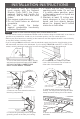
If you’re wiring a BUILT-IN model BTF or SBF thermostat for your heater, go to those instructions
now and follow that installation. When complete, proceed to OPERATING INSTRUCTIONS below.
If you’re wiring a WALL thermostat for your heater, FOLLOW THE INSTRUCTIONS BELOW and
the diagrams in Figures 10 or 11, depending on which side you’re wiring. Your electrical supply wires
should be routed from the circuit breaker to the wall thermostat, and then to the baseboard.
1. The heater must be properly
installed before it is used.
2. DANGER: High temperatures may
be generated under certain abnormal
conditions. Do not partially or fully cover
or obstruct the front of this heater.
Figure 11b
Figure 10b
DO NOT
CUT!
red wire capped
red wire
capped
red wire capped
red wire capped
red
wire
DO NOT CUT!
supply wires
supply
wires
supply
wires