
Installation Guide


INSTALLATION INSTRUCTIONS
5
Figure 10a
Figure 9a
DO NOT CUT!
Left Side of Baseboard Shown
2000 Watt Conguration / Heater is wired on right side
Left Side of Baseboard Shown
2000 Watt Conguration / Heater is wired on left side
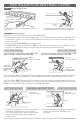
Cut the factory
connection without
the red wire.
A. Connect one
supply wire to one
heater wire.
B. Connect the
remaining supply
wire to the
remaining heater
wire.
All model 8F2025 model baseboard heaters are factory set for 2500 watts. If you want to change to
2000 watts, follow the diagrams in Figure 9b or 10b, depending on which side you’re wiring. If you do
not want to change your baseboard heater’s wattage, proceed to STEP 4 Finish installation.
• For 2000 watt applications: Cut red wire and cap both loose ends with wire connectors, or wrap
loose ends with electrical tape. Proceed to STEP 4 Finish installation.
Cut the factory
connection. Do not cut
any connections on
the left side.
A. Connect one
supply wire to one
heater wire.
B. Connect the
remaining supply
wire to the remaining
heater wire.
If you’re wiring a BUILT-IN model BTF or Smart-Base thermostat for your heater, go to those instruc-
tions now and follow that installation. When complete, proceed to OPERATING INSTRUCTIONS.
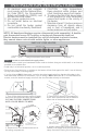
If you’re wiring a WALL thermostat for your heater, FOLLOW THE INSTRUCTIONS BELOW and the
diagrams in Figures 9a or 10a, depending on which side you’re wiring. Route your electrical supply
wires from the circuit breaker to the wall thermostat, and then to the baseboard heater.
Wrap
supply
(white)
wire with
black tape
to identify
it as hot!
Wrap supply (white) wire with black tape to identify it as hot!
Figure 7c Figure 8c
DO NOT CUT!
new
connection
new
new
connection
new connection
supply wires
supply wires
connection
120 volt baseboard 120 volt baseboard
B
B
A
A
A. For 120 volts, connect the neutral (white)
supply wire to the white heater wire.
B. Connect remaining supply wire to remaining
heater wire with a wire connector (not
included).
Screw wiring compartment cover(s) back on. Turn power back on at the main disconnect panel.
Proceed to OPERATING INSTRUCTIONS.
STEP 4
Finish installation
Proceed to STEP 4 Finish installation.
8F2025 ONLY - CHANGING WATTAGE
8F2025 ONLY
LEFT SIDE WIRING RIGHT SIDE WIRING
120 VOLT ONLY
LEFT SIDE WIRING RIGHT SIDE WIRING
Figure 10b
Figure 9b
DO NOT
CUT!
red wire capped
red wire
capped
red wire capped
red wire capped
red
wire
DO NOT CUT!
supply wires
supply
wires
supply
wires
A
B
A
B