
Specifications


INSTALLATION INSTRUCTIONS
1. All electrical work and materials must comply
with the National Electric Code (NEC), the Occu-
pational Safety and Health Act (OSHA), and all
state and local codes.
2. Use copper conductors only.
3. Do not install below an electrical receptacle.
4. Do not install the heater against combustible
low-density cellulose berboard.
5. A heater has hot and arcing or sparking parts
inside. Do not use it in areas where gasoline,
paint, or ammable vapors or liquids are used or
stored.
6. Heater should be set ush against surface of
the wall.
7. Remove any obstructions between the back of
the unit and the surface of the wall.
8. Baseboard heater may sit directly on any oor
surface, including carpet.
9. Maintain at least 12 inches minimum clearance
in front of baseboard, and from objects hanging
above (i.e., drapes), and 6 inches minimum on
both sides.
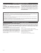
1. Locate wall studs closest to supply wires and position heater
(See Figure 1). NOTE: Wire connection is possible from either
right or left side of the baseboard heater.
IMPORTANT! DO NOT DISCONNECT ANY OF THE BASE-
BOARD’S FACTORY WIRE CONNECTIONS UNTIL YOU ARE
READY TO BEGIN WIRING!
STEP 1
Mount Heater to Wall
Figure 1
Figure 2
Figure 3
2. Remove the wiring compartment cover by removing the screw
(See Figure 2). The wiring compartment is an approved junction
box for the baseboard only. No additional junction box is required.
4. Pull supply wires through the connector and secure leaving 6
inch wire leads for later use (See Figure 4).
Figure 5
3. Remove the slotted knockout closest to the sup ply wires and
install a strain relief connector (See Figure 3).
5. Mount the heater securely to the wall with nails or screws going
into at least two wall studs (See Figure 5). The back of the heater
has “star punch” dimples that allow nails or screws to easily pierce
the sheet metal.
NOTE: You do not need to remove the front cover or disas-
semble any additional parts to mount the heater.
Figure 4
6. Connect the grounding lead to the grounding screw on which-
ever side you are wiring (See Figure 4). Both sides of the heater
include a grounding screw.
Page 3
Finished
Wall
Supply
Wire
Wall Studs
Floor
Wiring
Compartment
Cover
Junction
Box
Ground Screw
Supply Wires
Wiring
Compartment
Cover