
Specifications


INSTALLATION INSTRUCTIONS (continued)
AB
GROUND
DO NOT DISCONNECT
AB
GROUND
DO NOT DISCONNECT
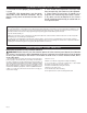
Refer to the wiring diagram below that corresponds to your heater application.
For all baseboards except Model 8F2025, refer to “Standard Baseboard.” For Model 8F2025, refer to “Multi-Watt Baseboard.”
(Important: connect supply ground wire directly to one of the ground screws provided on either side of the baseboard heater.)
Figure 8
Figure 9
RIGHT Side
Wiring Shown
Figure 6 Figure 7
STEP 2
Baseboard Wiring
1. Verify the electrical supply wires are the same voltage as the heater. Check heater specications to ensure correct wiring. Failure to
do so may destroy the heater and void your warranty. Both 120 volt and 240 volt baseboard wiring utilize three supply wires.
120 volt baseboard wiring: 1 hot, 1 neutral and 1 ground.
240 volt baseboard wiring: 2 hot and 1 ground. No neutral needed.
For all baseboard wiring applications, each of the supply wires must be connected to at least one (1) heater wire.
2. Disconnect ONLY ONE factory connector and ONLY on the side you will be wiring (See Figure 6; for Model 8F2025 See Figure 7). If
wiring on the left side, disconnect ONLY factory connector A. If wiring on the right side, disconnect ONLY factory connector B.
NOTE: There are no loose wires provided with the baseboard. This is due to the ability to wire the baseboard on either the right or left
side of the heater.
3. Proceed to the next step.
STANDARD BASEBOARD WIRING ON RIGHT SIDE
120V OR 240V SUPPLY (See Figure 8)
1. Connect one supply wire to one heater wire.
2. Connect remaining supply wire to remaining heater wire.
3. Replace wiring compartment cover and secure with screw previ-
ously removed.
4. Turn power back on at the electrical panel board.
STANDARD BASEBOARD WIRING ON LEFT SIDE
120V OR 240V SUPPLY (See Figure 9)
1. Connect one supply wire to one heater wire.
2. Connect remaining supply wire to remaining heater wire.
3. Replace wiring compartment cover and secure with screw previ-
ously removed.
4. Turn power back on at the electrical panel board.
MULTI-WATT BASEBOARD WIRING ON RIGHT SIDE
MODEL 8F2025 ONLY (See Figure 10)
1. Connect one supply wire to one heater wire.
2. Connect remaining supply wire to remaining heater wire.
3. Replace wiring compartment cover and secure with screw previ-
ously removed.
4. Selecting desired wattage:
a. For 2500 watt applications: No action is required. Heat-
er is factory set for 2500 watts.
b. For 2000 watt applications (inset): Remove left wiring
compartment cover. Cut red wire and cap both loose ends with
approved wire connectors, or wrap both loose ends with electrical
tape. Replace wiring compartment cover and secure with screw
previously removed.
5. Turn power back on at the electrical panel board.
Figure 10
LEFT Side
Wiring Shown
RIGHT Side
Wiring Shown
Model
8F2025
only
DO NOT DISCONNECT!
Page 4
Supply Wires
Ground Screw
Supply Wires
Ground Screw
To Supply
To Supply
Supply Wires
Ground Screw
2000 Watt Conguration
Left Side of Baseboard Shown
red wire
red
wire
To Supply
Baseboard Heater
Baseboard Heater
Baseboard Heater
Side A
Side B
Side B