
Patio Heater User Manual

2
Installation Instructions
READ ALL INSTRUC-
TIONS AND SAFETY
INFORMATION.
WARNING!
When working
with electricity,
turn the electrical
power off at the
electrical panel
board and lock or
tag the circuit
breaker door.
Failure to do so
could result in
serious electrical
shock, burns, or
possible death.
WARNING!
Risk of Fire. Heaters
must be kept clean
of lint, dirt and
debris.
Failure to follow
warnings may
cause heater to
eject sparks, ignite
materials, or cause
electrical shock.
Horizontal Delivery
Heaters should be located so that the air streams
of the individual units "wipe" the exposed walls of
the building without blowing directly against the
wall. Recommended spacing between the units
is 12 feet. Locate heaters so their air streams are
not subjected to interference from columns,
partitions, machinery, etc.
(See Figure 1)
Figure 1.
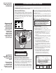
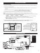
PLACEMENT: Install the CEH unit heater vertically or horizontally. Brackets are also available for ceiling mount
or wall mount applications.
THERMOSTAT: A line voltage OR low voltage thermostat is required for operation. A Cadet wall thermostat is
recommended for ultimate control and comfort.
HORIZONTAL VERTICAL
MODEL DISCHARGE DISCHARGE
CEH-003 9' 10'
CEH-005 9' 10'
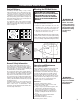
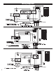
Figure 2. Horizontal mounting clearances with
optional bracket (CEK-M1).
MAXIMUM MOUNTING HEIGHT
(TO BOTTOM OF UNIT)
MIN. 6"
(15.2 CM)
MIN. 6"
(15.2 CM)
MIN. 10"
(3.3–5 KW Units)
(25.4 CM)
OPTIONAL
MOUNTING
BRACKET
1/2"
MOUNTING
BOLT
6
' TO FLOOR (MIN.
)
(2.13 M)
8' (2.44 M)
IN
CANADA
BACK
WALL
SIDE
WALL
CEILING
In an area where the air temperature will be main-
tained at less than 68˚F, the heater should be mount-
ed in a postion that will not blow directly on people
working in the area.
A minimum clearance for each heater (both hori-
zontal and vertical mount) is listed in Figure 2.
Please follow these recommendations to avoid
potential problems with the function and safety of the
heater.
Mounting the CEH Unit Heater
CAUTION:
THE CEILING OR WALL MOUNTING
STRUCTURE AND ANCHORING PROVISIONS
MUST BE OF SUFFICIENT STRENGTH TO
SUPPORT THE COMBINED WEIGHT OF THE
HEATER AND MOUNTING BRACKETS
Horizontal Discharge
(See Figure 2 for minimum clearances)
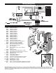
1. Mounting with rod from ceiling or super-
structure:
(Figure 3)
a. Remove the four factory installed bolts from
the top of the unit and screw them into the
threaded holes in the back.
b. Install four 5/16-18 threaded rods in holes
and secure in place using lock (jam) nuts.
(Figure 3)
c. Attach the four mounting rods to the ceiling
or overhead structure and anchor securely.
2. Mounting with optional bolt-on ceiling
brackets:
(Figure 2)
a. Bolt mounting bracket on top of unit using
the four factory installed bolts.
b. Suspend the unit from ceiling or overhead
structure using a 1/2 inch threaded rod or
bolt, allowing a minimum 6 inches clearance
from the ceiling. Using lock (jam) nut, anchor
securely.
3. Mounting with optional wall hanger arm and
mounting bracket:
(See Parts List items #10 & #11)
a. Bolt mounting bracket on top of unit using
four factory installed bolts.
b. Attach the wall hanger arm to wall using
four 3/8 inch bolts or masonry fasteners.
c. Suspend the unit from hanger arm using
1/2 inch bolt. Place the rubber washer
provided between the mounting brackets.
General Safety Information
The ceiling or wall on which the heater is to be
mounted must be of adequate strength to support the
heater. Plaster or suspended ceilings will not sup-
port this type of heater. For greater stability, we
recommend the use of threaded rods.
Do not mount the heater where volatile liquids or
gases will be present or where it will be exposed
to rain or mist. All combustible materials should
be kept at least 3 feet away from front of the heater.
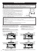
A
C
D
B
FRONT
5/16-18
Threaded
Mounting
Holes
UNIT KW ROD THREAD A B C D
3.3, 5.0 5/16-18 6" (15.2CM) 6.75" 4.04" 0.75"
Figure 3. Horizontal discharge rod spacing
MOUNTING ROD DIMENSIONS