
Patio Heater User Manual

3
Installation Instructions
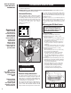
WARNING!
Risk of Electrical
Shock. Turn off all
power at the electri-
cal panel board sup-
plying power to the
heater before doing
any electrical
wiring.
WARNING!
Overheating or fire
may occur. DO NOT
place the heater
behind doors.
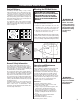
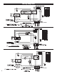
Vertical Delivery
In buildings with high ceilings or bays, vertical
delivery unit heaters are recommended to produce
comfort in central areas. They are best used when
the perimeter heat loss is adequately controlled. In
combination with horizontally discharged units,
they aid in providing good air mixture (See Figure 4).
Vertical discharging units are mounted high above
machinery, assembly lines, etc.
In an application where only vertical discharging
units will be used, the air streams must overlap to
blanket outside walls and provide good heat distri-
bution (See Figure 5).
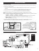
Mounting the CEH Unit Heater
CAUTION:
THE CEILING OR WALL
MOUNTING STRUCTURE AND ANCHORING
PROVISIONS MUST BE OF SUFFICIENT
STRENGTH TO SUPPORT THE COMBINED
WEIGHT OF THE HEATER AND MOUNTING
BRACKETS
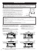
Vertical Discharge
(See Figure 6 for minimum clearances)
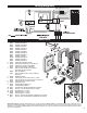
1. Install four 5/16-18 threaded rods into the
threaded holes in the back of the heater and
secure in place using lock (jam) nuts (Figure 7).
2. Attach the four mounting rods to ceiling or over-
head structure and anchor securely.
NOTE: When mounting for vertical discharge,
position unit so that access door opens away
from nearest wall. This permits maximum
access to wiring compartment (Figures 2 & 6).
Figure 4.
Figure 5.
Figure 6. Ceiling mount. Vertical mounting clearances.
General Safety Information
The ceiling or wall on which the heater is to be
mounted must be of adequate strength to support
the heater. Plaster or suspended ceilings will not
support this type of heater. For greater stability, we
recommend the use of threaded rods.
Do not mount the heater where volatile liquids or
gases will be present or where it will be exposed to
rain or mist. All combustible materials should be
kept at least 3 feet away from front of the heater.
In an area where the air temperature will be main-
tained at less than 68˚F, the heater should be mount-
ed in a position that will not blow directly on people
working in the area.
A minimum clearance for each heater (both hori-
zontal and vertical mount) is listed in Figure 6.
Please follow these recommendations when
mounting to avoid potential problems with the func-
tion and safety of the heater.
E
H
G
F
5/16-18
Threaded
Mounting
Holes
BACK
Figure 7.
Vertical discharge rod spacing
UNIT KW
ROD THREAD
EF G H
3.3, 5.0 5/16-18 6" (15.2 CM) 9.63" (24.5 CM) 4.04" (10.3 CM) 2.10" (5.3 CM)
MOUNTING ROD DIMENSIONS
Operation and Maintenance
How to operate your heater
Turn your built-in or wall thermostat to the desired
setting. The heater will run for approximately
twenty seconds before the fan comes on. The
heater will then run until the thermostat setting is
reached. Fan will continue to run with elements
shut off for approximately seventy seconds and
then will shut off. This cycle will continue as need-
ed based on thermostat setting. Do not use break-
er panel or fuse box to control heater. Be sure
power to heater is constant all the time.
Maintenance
1. Shut off circuit breaker to heater.
2. Remove front diffuser grill or 3 of the center
louvers in front of fan area.
3. Using a compressor, blow air through the outer
cabinet louvers and finned element areas.
(Do not touch sharp surfaces on elements).
While holding fan blade (to avoid damage or
bending) carefully blow inside the fan motor
area.
4. Carefully wipe off the fan blade without
damaging or bending it.
5. Reinstall front diffuser or air vanes.
6. Restore power to heater.