
Patio Heater User Manual

4
Wiring Instructions
Branch Circuit Connections (Power)
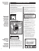
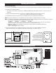
1. Wiring compartment access door is hinged. To open, turn single screw on the side 1/4
turn (see Figure 8). Do not try to remove screw.
2. A knockout is provided in the back of the unit for field wiring (See Figure 8). This is a
multiple diameter knockout. Use the diameter that fits the required conduit size.
3. A ground terminal is provided near the junction block for field wiring. The ground
should be connected before any other connections.
4. The junction block is equipped with box terminals sized to accept the correct power
supply wire. Wire rated at 600 volts and 75˚C is satisfactory for branch circuit
connections. Either copper or aluminum conductors may be used. NOTE: the center
box terminal on the three pole junction block is used only for 3-phase operation.
5. Each heater has a wiring diagram on the inside of the access door. Consult this
diagram before making any field connections.
DUAL RATED 240/208 VOLT MODELS: All 240 volt models may be
operated at 208 volts with a corresponding reduction in output. When
the heater is connected to a 208 volt power supply, disconnect the
transformer lead from the terminal marked 240V and connect it to the
terminal marked 208V. 277 volt units may only be used on single phase
circuits. 480 volt units may only be used on three phase circuits.
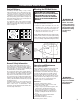
3-Phase Connections
Single or 3-phase power connections may be used on all 208 and
240/208 volt, 3.3–5 KW models. These units come factory wired for
single-phase power but may be wired for 3-phase power by recon-
necting two wires. This is done as follows:
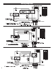
1. Models with Line Voltage Control
(See Figures 9 & 10)
a. Disconnect the orange wire from the junction block terminal
and connect it to the orange wire on the small terminal block and,
b. Disconnect the red wire from the junction block and connect it
to the terminal in the center of the block.
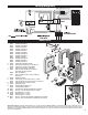
2. Models with 24 Volt Control
(see Figures 11 & 12)
a. Disconnect the orange wire from the junction block
terminal and connect it to the orange wire on the contactor
terminal and,
b. Disconnect the red wire from the junction block and
connect it to the terminal in the center of the block.
CAUTION:
TO AVOID ELECTRICAL SHOCK, BE SURE ELECTRICITY IS TURNED OFF AT ELECTRICAL PANEL BOARD BEFORE WIRING.
ALL WIRING MUST BE DONE IN ACCORDANCE WITH LOCAL CODES AND THE HEATER MUST BE GROUNDED AS A PRECAUTION AGAINST
POSSIBLE ELECTRIC SHOCK. IN ABSENCE OF LOCAL CODES, FIELD WIRING TO THE UNIT SHALL COMPLY WITH CURRENT PROVI-
SIONS OF THE AMERICAN NATIONAL ELECTRICAL CODE OR YOUR NATIONAL ELECTRICAL CODE, AS APPLICABLE.
NOTE:
Connect heater only to a line with the voltage and frequency specified on the nameplate.
CAUTION – READ THESE INSTRUCTIONS CAREFULLY WHEN USING ALUMINUM WIRING
1. Carefully strip insulation from aluminum conductors and coat ends of conductors with suitable corrosion inhibitor ("Pentrox A"
or equivalent).
2. Wire brush aluminum surface, removing corrosion; re-coat with corrosion inhibitor.
3. Connect aluminum wiring and tighten connection securely. CAUTION: Do not exceed pressure needed for making a typical copper
connection.
4. Coat entire connection with inhibitor.
5. All connections using aluminum conductors should be periodically re-checked for tightness.
6. NOTE: DO NOT JOIN ALUMINUM CONDUCTORS DIRECTLY TO COPPER.
Power
Wiring
Knockout
Hinge
1/4 Turn Captive Fastener
Access Door
BACK
Figure 8.
Knockout locations
Control
Wiring
Knockout
Heater
elements
Orange
wire
Orange
wire
Junction block
for field wiring
Red
wire
Terminal
block
Heater
elements
Orange
wire
Orange
wire
Junction block
for field wiring
Red
wire
Terminal
block
FRONT
BACK
Heater
elements
Orange
wire
Orange
wire
Junction block
for field wiring
Red
wire
Terminal
block
Contactor
FRONT
BACK
Heater
elements
Orange
wire
Orange
wire
Junction block
for field wiring
Red
wire
Terminal
block
Contactor
FRONT
BACK
FRONT
BACK
Factory wired for
single phase
power (line
voltage control
models).
Factory wired for
3-phase power
(line voltage
control models).
Factory wired for
single phase
power (24 volt
control models).
Factory wired for
3-phase power
(24 volt control
models).
NOTE: Supply wires must feed direct from breaker to junction block. Thermostat wires connect to terminal board. See
wiring diagrams for your specific model.
Figure 9.
Figure 12.
Heater
elements
Orange
wire
Orange
wire
Junction block
for field wiring
Red
wire
Terminal
block
FRONT
BACK
Factory wired for
3-phase power
(line voltage
control models).
Figure 10.
Heater
elements
Orange
wire
Orange
wire
Junction block
for field wiring
Red
wire
Terminal
block
Contactor
FRONT
BACK
Factory wired for
single phase
power (24 volt
control models).
Figure 11.