
Patio Heater User Manual

5
H
1
H
2
P
1
P
2
F
2
F
1
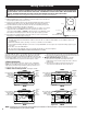
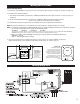
Control Voltage Wiring
1. A knockout is also provided in the back of the unit for control wiring. This knockout is sized for 1/2" conduit. (see Figure 13)
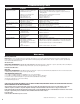
2. Thermostat wire shall be as follows:
a. Line voltage control models: Use NEC Class 1, 600V, 90˚C, AWG #10 wire with copper conductor or same gauge wire as
supply line.
b. 24 volt control models (B package): Use NEC Class 1, 600V, 90˚C, AWG #18 wire with copper conductor.
Use H1 + P1, terminals for connection (Do not use jumpers).
3. Install wall thermostats in accordance with the installation instructions supplied with the thermostat.
NOTE: Do not locate thermostat in an area exposed to unusual temperature conditions or poor air circulation.
NOTE: a.Line voltage control models of 3.3KW and 5.0KW ratings that are 208 and 240 volt, wired for 3-phase operation, should not
be used with a wall thermostat. This applies to the following models:
CEH-003-M CEH-003-P CEH-005-M CEH-005-P
These models come factory wired for single phase. When these models are converted in the field to 3-phase, DO NOT USE A WALL MOUNTED
THERMOSTAT. Thermostat control for 3-phase hookup should be provided by a CEK-TB2 (built-in thermostat).
b.When using model number CEH-005-M wired single phase (factory wired) use the following thermostats:
Wall Mount – C611-25,
Built-In – CEK-TB2 (two-stage thermostat)
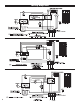
4. Connect the thermostat wires to terminals H1 and P1 as shown in Figure 13. On 208 and 240 volt, single-phase
models with line voltage control, (Not B package models) install jumpers as shown in Figure 13.
Figure 13. Thermostat wiring connections
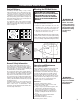
Figure 14.
Manual reset limit
A manual reset thermal limit is
factory installed on all models.
The limit is located on the front of
the heater. The manual reset limit
will not reset until the button is
pushed and heater has cooled
down. (208/240V line voltage con-
trol heaters use two manual reset
limits
)
FRONT
BACK FRONT
Line Voltage
Control Models
(Singe Phase):
Install jumpers
between H
1
and H
2
and P
1
and P
2
on
208/240V units
(note dashed lines).
Manual Reset Limit
Heater Elements
Control Terminal Board
Connect Thermostat
Wires To P
1
and H
1
To Thermostat
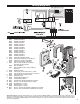
Wiring Instructions
Wiring Diagrams