
Owner Manual


INSTALLATION INSTRUCTIONS (continued)
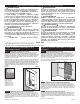
RB/RBF
Wall Can
Heater Assembly
Spring Clip
Grill
Grill Frame
Grill Screw
Washer
Heater Assembly Screw
Rocker Switch
Supply
Wires
_________
Retrotting RBF101 as Replacement for RB Heaters
_________
Remove Existing Heater
STEP 1
A. WARNING! Before removing grill, turn the electrical power off at the main disconnect panel (circuit breaker or fuse box). Lock or tag
the main disconnect panel door to prevent someone from accidentally turning the power on while you are working on the heater. Failure
to do so could result in serious electrical shock, burns, or possible death.
B. It is important that you verify power has been turned off and the heating element is cool before proceeding. Circuit breakers are often
not marked correctly and turning the wrong breaker off could mean electricity is owing to the heater, even if the heater does not appear
to be working. If you are uncomfortable working with electrical appliances, unable to follow these guidelines, or do not have the neces-
sary equipment, consult a qualied electrician.
C. Once you verify the power has been turned off correctly, proceed to next step.
D. Remove screws and take off grill.
E. Separate supply wire and lead wire connections.
Proceed to Part Two.
__________________________
Part Two
__________________________
After you have followed all instructions in Part One or Retrotting, you are ready to install
the heater assembly.
STEP 1
STEP 1
Install Heater Assembly
STEP 1
Install Grill Frame and Grill
STEP 2
Remove protective lm from frame and grill before installing. Place grill frame outside top and bottom anges of the heater assembly.
Place grill over frame and secure with the four nishing washers and four #10 x 1½ inch Phillips oval head sheet metal screws (See
Figure 4). Start all four screws before tightening (Note: Over tightening screws may damage grill).
Install spring clips on wall can edge, two at the top and two at the bottom (See Figure 4). Lay heater assembly on its front surface and
position so rocker switch will be installed at bottom of wall can (See Figure 5). Make the connection of the supply wires to the lead wires
from the rocker switch. Position the heater assembly to t adapter plate to the surface of the wall can (See Figure 4). Be sure all lead
wires are inside the wall can before securing heater assembly. (Use the four #10 32 x ½ inch machine screws; two at top and two at
bottom.)
Figure 4
Figure 5
How do I insert the heater assembly into the wall can?
Page 4