
User's Manual
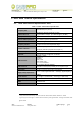
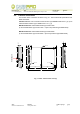
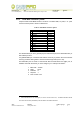

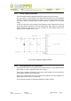
Table Of Contents
- 1. Introduction
- 2. Mod. A528 Technical Specifications
- 2.1. Mod. A528 Technical Specifications Table
- 2.2. External connections
- 2.2.1. A528 Main connector pinout
- 2.2.2. A528 MAIN connector electrical characteristics
- 2.2.3. Power supply connection
- 2.2.4. General purpose I/O connections
- 2.2.5. External reset
- 2.2.6. UART connection
- 2.2.7. A528 recovery
- 2.2.8. A528 USB connector pinout
- 2.2.9. USB connector pinout electrical characteristics
- 2.2.10. Antenna port specifications
- 2.3. Reader – Tag link profiles
- 2.4. Host communication interfaces
- 2.5. A528 Firmware Upgrade

Document type: Title: Revision date: Revision:
User's Manual (MUT) Mod. A528 OEM UHF Multiregional compact reader 02/04/2008 2
2.2.3. Power supply connection
In the following schematic suggested A528 power supply connection is shown.
The use of fuse F1 is recommended since A528 doesn't provide internal current limitation
protection. Diode D1 avoid damage to the reader in case of reverse polarity connection.
The use of optional LC filter improves reader immunity in presence of noisy power
supply.
In order to ensure the correct operation of the reader the power supply shall not enter in
burst mode (switching frequency less than 100kHz) when A528 reader is in idle mode
(supply current less than 0.2A). As a rule of thumb the power adapter shall have a
maximum current rating from 1A to 1.5A.
Fig. 2-2: Mod. A528 power supply connection
2.2.4. General purpose I/O connections
The GPIO0-GPIO3 pins are 4 general-purpose bidirectional pins. Their default direction
after a power on reset or a general reset is set to Output.
GPIO, when configured as Outputs, can be used to drive indicators as leds or buzzers or
to send trigger signal to others equipments.
GPIO, when configured as Inputs, can accept control signals from other equipments or
trigger signals from sensors (i.e. photocells).
In the following schematic an example of application of GPIO is shown.
NPO: Filename: Number of pages: Page:
00101/07:A528X.MUTx/02 A528_REV02.DOC 19 10