
User's Manual
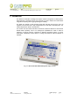
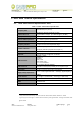

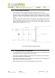
Table Of Contents
- 1. Introduction
- 2. Mod. A528 Technical Specifications
- 2.1. Mod. A528 Technical Specifications Table
- 2.2. External connections
- 2.2.1. A528 Main connector pinout
- 2.2.2. A528 MAIN connector electrical characteristics
- 2.2.3. Power supply connection
- 2.2.4. General purpose I/O connections
- 2.2.5. External reset
- 2.2.6. UART connection
- 2.2.7. A528 recovery
- 2.2.8. A528 USB connector pinout
- 2.2.9. USB connector pinout electrical characteristics
- 2.2.10. Antenna port specifications
- 2.3. Reader – Tag link profiles
- 2.4. Host communication interfaces
- 2.5. A528 Firmware Upgrade

Document type: Title: Revision date: Revision:
User's Manual (MUT) Mod. A528 OEM UHF Multiregional compact reader 02/04/2008 2
2.2.1. A528 Main connector pinout
Compact reader A528 MAIN external connector is a Molex SMD, 12 poles, 1.27 pitch
connector whose pinout is shown in table below.
Table 2: A528 MAIN connector pinout
Pin Function Direction
1 Power Line (+5V) -
2 /RESET IN
3 GPIO0 IN/OUT
4 GPIO1 IN/OUT
5 GPIO2 IN/OUT
6 GPIO3 IN/OUT
7 TST_RECOVERY IN
8 USB PUP IN
9 RXD IN
10 TXD OUT
11 GND -
12 GND -
The GPIO0-GPIO3 pin are 4 general purpose bidirectional pins, their default direction (or
after a Reset) is OUT.
TST_RECOVERY pin is reserved and shall be used only to perform the microcontroller
recovery procedure during which it must be forced at high level (3.3V or 5V).
The RXD/TXD pins are used to communicate with the A528 board via UART port; to
establish a link with the device you must configure your COM port as follows
3
:
1. Baud rate : 115200
2. Parity : None
3. Data bits : 8
4. Stop bits : 1
5. Flow Control: none
3
Since A528 RX/TX are TTL level signals, in order to connect it with a PC, a TTL/RS232 translator shall be
used. A528 service board (A528ADAT) hosts both RS232 and USB full interfaces.
NPO: Filename: Number of pages: Page:
00101/07:A528X.MUTx/02 A528_REV02.DOC 19 8