Installation Instructions Over the Range Microwave Oven BEFORE YOU BEGIN Read these instructions carefully and completely. Ŷ IMPORTANT – Save these instructions for Ŷ Note to Consumer – Keep these instructions for future reference. IMPORTANT – Observe all governing codes Ŷ Skill level – Installation of this appliance requires basic mechanical and electrical skills. local inspector’s use. Ŷ and ordinances. Ŷ Note to Installer – Be sure to leave these instructions with Consumer.
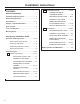
Installation Instructions B Outside Back Exhaust ............................16-19 CONTENTS General information 3UHSDULQJ 5HDU :DOO IRU Outside Back Exhaust ........................ 16 Important Safety Instructions .............................. 3 $WWDFK 0RXQWLQJ 3ODWH WR :DOO .......16 17 Electrical Requirements........................................ 3 3UHSDUDWLRQ RI 7RS &DELQHW ................ 17 Hood Exhaust ....................................................
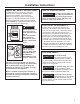
Installation Instructions IMPORTANT SAFETY INSTRUCTIONS A qualified electrician must perform a ground FRQWLQXLW\ FKHFN RQ WKH ZDOO UHFHSWDFOH EHIRUH beginning the installation to ensure that the RXWOHW ER[ LV SURSHUO\ JURXQGHG ,I QRW SURSHUO\ grounded, or if the wall receptacle does not meet HOHFWULFDO UHTXLUHPHQWV QRWHG XQGHU (/(&75,&$/ 5(48,5(0(176 D TXDOLILHG HOHFWULFLDQ VKRXOG EH HPSOR\HG WR FRUUHFW DQ\ GHILFLHQFLHV WARNING Risk of Electric Shock.
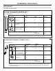
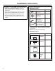
Installation Instructions HOOD EXHAUST 127( 5HDG WKHVH QH[W WZR SDJHV RQO\ LI \RX SODQ WR YHQW \RXU H[KDXVW WR WKH RXWVLGH ,I \RX SODQ WR UHFLUFXODWH WKH DLU EDFN into the room, proceed to page 11. OUTSIDE TOP EXHAUST (EXAMPLE ONLY) 7KH IROORZLQJ FKDUW GHVFULEHV DQ H[DPSOH RI RQH SRVVLEOH ductwork installation.
Installation Instructions NOTE: ,I \RX QHHG WR LQVWDOO GXFWV QRWH WKDW WKH WRWDO duct length of 31»4Ǝ [ Ǝ UHFWDQJXODU RU Ǝ GLDPHWHU URXQG duct should not exceed 140 equivalent feet. 2XWVLGH YHQWLODWLRQ UHTXLUHV D +22' (;+$867 '8&7 5HDG WKH IROORZLQJ FDUHIXOO\ NOTE: It is important that venting be installed using the most direct route and with as few elbows as possible. 7KLV HQVXUHV FOHDU YHQWLQJ RI H[KDXVW DQG KHOSV SUHYHQW blockages.
Installation Instructions DAMAGE – SHIPMENT INSTALLATION • If the unit is damaged in shipment, return the unit to the store in which it was bought for repair or replacement. • If the unit is damaged by the customer, repair or UHSODFHPHQW LV WKH UHVSRQVLELOLW\ RI WKH FXVWRPHU • If the unit is damaged by the installer (if other WKDQ WKH FXVWRPHU UHSDLU RU UHSODFHPHQW PXVW EH PDGH E\ DUUDQJHPHQW EHWZHHQ FXVWRPHU DQG installer.
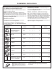
Installation Instructions TOOLS YOU WILL NEED 5XOHU RU WDSH PHDVXUH and straight edge 3HQFLO DQG 3KLOOLSV screwdriver 7LQ VQLSV IRU FXWWLQJ GDPSHU LI UHTXLUHG Scissors (to cut template, if QHFHVVDU\ Electric drill with 3»16s, 1»2s and 5»8s drill bits Gloves Saw (saber, hole or NH\KROH /HYHO MOUNTING SPACE 161»2s 30s 2s 30s min.
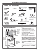
Installation Instructions 1 PLACEMENT OF THE MOUNTING PLATE A. REMOVING THE MICROWAVE OVEN FROM THE CARTON/REMOVING THE MOUNTING PLATE B. FINDING THE WALL STUDS 1 5HPRYH WKH LQVWDOODWLRQ LQVWUXFWLRQV ILOWHUV JODVV WUD\ DQG WKH VPDOO KDUGZDUH EDJ 'R QRW UHPRYH the foam protecting the front of the oven. 2 )ROG EDFN DOO FDUWRQ IODSV IXOO\ DJDLQVW FDUWRQ VLGHV 7KHQ FDUHIXOO\ UROO WKH RYHQ DQG FDUWRQ RYHU RQWR WKH WRS VLGH 7KH RYHQ VKRXOG EH UHVWLQJ LQ the foam.
Installation Instructions C.
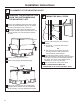
Installation Instructions D. ALIGNING THE WALL PLATE +ROH $ +ROH & Centerline 1RWFKHV Area E CAUTION Wear gloves to avoid cutting fingers on sharp edges. 1 Draw a vertical line on the wall at the center of the 30s wide space. 2 8VH WKH PRXQWLQJ SODWH as the template for the rear ZDOO 3ODFH WKH PRXQWLQJ SODWH RQ WKH ZDOO PDNLQJ sure that the tabs are touching the bottom of the cabinet or the level line drawn in Step C for cabinets with front overhang.
Installation Instructions 2 INSTALLATION TYPES (Choose A, B or C) 7KLV PLFURZDYH RYHQ LV GHVLJQHG IRU DGDSWDWLRQ WR WKH IROORZLQJ WKUHH W\SHV RI YHQWLODWLRQ A. Outside Top Exhaust (Vertical Duct) B. Outside Back Exhaust (Horizontal Duct) C.
Installation Instructions A OUTSIDE TOP EXHAUST (Vertical Duct) INSTALLATION OVERVIEW A1. $WWDFK 0RXQWLQJ 3ODWH WR :DOO A2 3UHSDUH 7RS &DELQHW A3. Check Blower Motor Oientation A4. Adapt Blower for Outside Ventilation A5. Check Damper Operation A6. Mount Microwave Oven A7. Adjust Exhaust Adaptor A8.
Installation Instructions A2. USE TOP CABINET TEMPLATE FOR PREPARATION OF TOP CABINET A4. ADAPTING BLOWER FOR OUTSIDE VENTILATION (Cont.) You need to drill holes for the top support screws, a hole large enough for the power cord to fit through, and a cutout large enough for the exhaust adaptor.
Installation Instructions A4. ADAPTING BLOWER FOR OUTSIDE VENTILATION (Cont.) A6. MOUNT THE MICROWAVE OVEN 7 3ODFH WKH EORZHU XQLW EDFN LQWR WKH RSHQLQJ Do not pull or stretch the blower unit wiring. Make sure the wires are not pinched. CAUTION FOR EASIER INSTALLATION AND PERSONAL SAFETY, WE RECOMMEND THAT TWO PEOPLE INSTALL THIS MICROWAVE OVEN. CAUTION IMPORTANT: Do not grip or use handle during installation. 8 Close the blower door. Secure the blower to the microwave using the screws from Step 1.
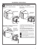
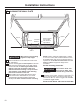
Installation Instructions A6. MOUNT THE MICROWAVE OVEN (cont.) A7. ADJUST THE EXHAUST ADAPTOR Open the top cabinet and adjust the exhaust adaptor to connect to the house duct. Cabinet Front Cabinet Bottom Shelf Filler Block Damper Back of Microwave Oven Equivalent to Depth of Cabinet 5HFHVV Self-Aligning Screw 0LFURZDYH 2YHQ 7RS For Side-to-Side Adjustment, Slide the Exhaust Adaptor as 1HHGHG 4 Attach the microwave oven to the top cabinet.
Installation Instructions B OUTSIDE BACK EXHAUST (Horizontal Duct) INSTALLATION OVERVIEW B1. 3UHSDUH 5HDU :DOO B2. $WWDFK 0RXQWLQJ 3ODWH WR :DOO B3. 3UHSDUH 7RS &DELQHW B4. Adjust Blower B5. Mount the Microwave Oven B1. PREPARING THE REAR WALL FOR OUTSIDE BACK EXHAUST You need to cut an opening in the rear wall for outside exhaust. B2. ATTACH THE MOUNTING PLATE TO THE WALL B A C D Attach the plate to the wall using toggle bolts.
Installation Instructions To use toggle bolts: Mounting 3ODWH B4. ADAPTING MICROWAVE 6SDFLQJ IRU 7RJJOHV 0RUH 7KDQ :DOO 7KLFNQHVV 7RJJOH :LQJV 7RJJOH Bolt Wall BLOWER FOR OUTSIDE BACK EXHAUST 1 5HPRYH DQG VDYH screws that holds blower motor to microwave oven. %ORZHU 5HWDLQLQJ Screws Bolt End 3 3ODFH WKH PRXQWLQJ SODWH DJDLQVW WKH ZDOO DQG insert the toggle wings into the holes in the wall to mount the plate.
Installation Instructions B4. ADAPTING MICROWAVE BLOWER FOR OUTSIDE BACK EXHAUST (cont.) 5 *HQWO\ UHPRYH WKH ZLUHV IURP WKH JURRYHV 5HURXWH WKH ZLUHV WKURXJK JURRYHV RQ RWKHU VLGH of the blower unit. %HIRUH 5HURXWLQJ 8 3ODFH WKH EORZHU XQLW EDFN LQWR WKH RSHQLQJ 7KH EORZHU XQLW H[KDXVW RSHQLQJV VKRXOG match exhaust openings on rear of microwave. CAUTION Do not pull or stretch the blower unit wiring. Make sure the wires are not pinched.
Installation Instructions B5. MOUNT THE MICROWAVE OVEN Cabinet Front Cabinet Bottom Shelf Filler Block Equivalent to Depth of Cabinet 5HFHVV Self-Aligning Screw FOR EASIER INSTALLATION AND PERSONAL SAFETY, WE RECOMMEND THAT TWO PEOPLE INSTALL THIS MICROWAVE OVEN. 4 Attach the microwave oven to the top cabinet. IMPORTANT: Do not grip or use handle during installation.
Installation Instructions C RECIRCULATING (Non-Vented Ductless) INSTALLATION OVERVIEW C1. $WWDFK 0RXQWLQJ 3ODWH WR :DOO C2. 3UHSDUH 7RS &DELQHW C3. Check Blower Motor Orientation C4. $GDSW %ORZHU IRU 5HFLUFXODWLRQ C5. Mount the Microwave Oven C6. Install Charcoal Filter C1 ATTACH THE MOUNTING PLATE TO THE WALL B A 3 3ODFH WKH PRXQWLQJ SODWH DJDLQVW WKH ZDOO DQG insert the toggle wings into the holes in the wall to mount the plate.
Installation Instructions C3. CHECK BLOWER MOTOR ORIENTATION 1 7KH EORZHU IDQ EODGH RSHQLQJ VKRXOG EH IDFLQJ the front of the microwave. If the fan opening is DOUHDG\ IDFLQJ WKH IURQW RI WKH PLFURZDYH VNLS to Step C5. Otherwise, continue to Step C4 to adjust the blower orientation. 4 5ROO WKH EORZHU XQLW VR WKDW IDQ EODGH RSHQLQJV are facing toward the front of the microwave. BEFORE: Fan Blade Openings Facing Up C4.
Installation Instructions C4. ADAPTING MICROWAVE BLOWER FOR RECIRCULATION (cont.) C5. MOUNT THE MICROWAVE OVEN 6 5HPRYH WKH PHWDO YHQW IDQ FRYHU RQ WKH EDFN RI WKH PLFURZDYH E\ VOLGLQJ LW XS FOR EASIER INSTALLATION AND PERSONAL SAFETY, WE RECOMMEND THAT TWO PEOPLE INSTALL THIS MICROWAVE OVEN. CAUTION 7 Close the blower door. Slide blower shield onto the top of the blower door opening. IMPORTANT: Do not grip or use handle during installation.
Installation Instructions C5. MOUNT THE MICROWAVE OVEN (cont.) 3 Insert a self-aligning screw through top center FDELQHW KROH 7HPSRUDULO\ VHFXUH WKH RYHQ E\ turning the screw at least two full turns after the threads have engaged. (It will be FRPSOHWHO\ WLJKWHQHG ODWHU Be sure to keep power cord tight. Be careful not to pinch the cord, especially when mounting flush to bottom of cabinet. C6. CHARCOAL FILTER A charcoal filter is installed in all units. Follow the steps below to check the filter.
Installation Instructions BEFORE YOU USE YOUR MICROWAVE 1. Make sure the microwave oven has been installed according to instructions. 2. HPRYH DOO SDFNLQJ PDWHULDO IURP WKH 5 microwave oven. 3. ,QVWDOO WXUQWDEOH DQG ULQJ LQ FDYLW\ 4. 5HSODFH KRXVH IXVH RU WXUQ EUHDNHU EDFN RQ 5. 3OXJ SRZHU FRUG LQWR D GHGLFDWHG WR 20-amp electrical outlet. 6. 5HDG WKH 2ZQHU¶V 0DQXDO 7. .
Instrucciones de instalación Horno microondas para colocar encima de la estufa ANTES DE COMENZAR Lea estas instrucciones por completo y con detenimiento. Ŷ IMPORTANTE – Guarde estas instrucciones para el uso del inspector local. Ŷ IMPORTANTE – Cumpla con todos los códigos y ordenanzas gubernamentales. Ŷ Nota para el instalador – Asegúrese de dejar estas Ŷ 1LYHO GH GHVWUH]DV ± /D LQVWDODFLyQ GH HVWH DSDUDWR UHTXLHUH de destrezas básicas de mecánica y electricidad.
Instrucciones de instalación CONTENIDO Información general Instrucciones de seguridad importantes ............ 3 Requisitos eléctricos ............................................ 3 Campana de escape .......................................... 4, 5 Cómo preparar la pared posterior para el escape posterior exterior ........ 16 Cómo adherir el plato de montaje a la pared ......................................16, 17 Cómo preparar el gabinete superior ... 17 Partes incluidas ...................................
Instrucciones de instalación INSTRUCCIONES DE SEGURIDAD IMPORTANTES Un electricista calificado debe realizar una YHULILFDFLyQ GH FRQWLQXLGDG GH FRQH[LyQ D WLHUUD en el tomacorriente de pared antes de comenzar OD LQVWDODFLyQ SDUD JDUDQWL]DU TXH OD FDMD GH distribución tenga una adecuada conexión a tierra.
Instrucciones de instalación CAMPANA DE ESCAPE NOTA: Lea las siguientes dos páginas solamente si planea ventilar el escape hacia el exterior. Si por el contrario planea recircular el aire de vuelta hacia el salón, continúe en la página 11. ESCAPE SUPERIOR EXTERNO (EJEMPLO SOLAMENTE) /D VLJXLHQWH WDEOD GHVFULEH XQ HMHPSOR GH XQD SRVLEOH instalación de red de conductos.
Instrucciones de instalación NOTA: Si usted necesita instalar conductos, tenga SHQGLHQWH TXH OD ORQJLWXG WRWDO GHO FRQGXFWR UHFWDQJXODU GH 31»4Ǝ [ Ǝ R HO FRQGXFWR UHGRQGR GH Ǝ GH GLiPHWUR no debe sobrepasar 140 pies equivalentes.
Instrucciones de instalación DA—OS – ENVÍO / INSTALACIÓN • Si la unidad se daña durante el envío, GHYXHOYD OD XQLGDG DO DOPDFpQ GRQGH OD DGTXLULy SDUD VX reparación o reemplazo. • Si el cliente daña la unidad, la reparación o el reemplazo es responsabilidad del cliente. • Si el instalador daña la unidad VL QR HV HO FOLHQWH OD UHSDUDFLyQ R UHHPSOD]R VH GHEH KDFHU por medio de un arreglo entre el cliente y el instalador.
Instrucciones de instalación HERRAMIENTAS QUE NECESITARÁ Regla recta y cinta PpWULFD /iSL] 'HVWRUQLOODGRUHV GH estrella #1 y #2 7LMHUDV SDUD FRUWDU ODWyQ SDUD FRUWDU HO UHJXODGRU GH WLUR VL HV QHFHVDULR 7LMHUDV SDUD FRUWDU OD SODQWLOOD VL HV QHFHVDULR Escuadra de carpintero RSFLRQDO 7DODGUR HOpFWULFR FRQ EURFDV de 3»16Ǝ 1»2Ǝ \ 5»8Ǝ Guantes 6LHUUD GH VDEOH DJXMHUR R GH RMR GH FHUUDGXUD 'HWHFWRU GH SRVWHV XQ PDUWLOOR RSFLRQDO GH YLJD R Gafas de seguridad 1LYHO %ORTXHV GH UHOOHQR R
Instrucciones de instalación 1 CÓMO COLOCAR EL PLATO DE MONTAJE A. CÓMO REMOVER EL HORNO MICROONDAS DEL EMBALAJE / CÓMO REMOVER EL PLATO DE MONTAJE B. CÓMO ENCONTRAR LOS POSTES DE VIGA EN LA PARED 1 5HPXHYD ODV LQVWUXFFLRQHV GH LQVWDODFLyQ ORV ILOWURV OD EDQGHMD GH FULVWDO \ OD EROVD SHTXHxD GHO HTXLSR 1R UHPXHYD HO SURWHFWRU IURQWDO GH espuma de poliestireno del horno. 2 'REOH WRWDOPHQWH KDFLD DWUiV ODV FXDWUR WDSDV de cartón hacia los lados opuestos de la caja.
Instrucciones de instalación C.
Instrucciones de instalación D. CÓMO ALINEAR EL PLATO DE MONTAJE SOBRE LA PARED Agujero A Muescas Agujero C de la línea del centro 7UDFH XQD OtQHD YHUWLFDO en la pared a partir del centro del gabinete superior Agujero B $JXMHUR ' Area E Use guantes de protección para evitar cortaduras en sus dedos con los extremos filosos.
Instrucciones de instalación 2 TIPOS DE INSTALACIÓN (Escoja A, B o C) Este horno microondas está diseñado para adaptarse a ORV VLJXLHQWHV WUHV WLSRV GH YHQWLODFLyQ A. Escape superior exterior (Conducto vertical) B. Escape posterior exterior (Conducto horizontal) C.
Instrucciones de instalación A ESCAPE SUPERIOR EXTERIOR (Conducto vertical) PERSPECTIVA GENERAL DE LA INSTALACIÓN A1. Cómo adherir el plato de montaje a la pared A2. Prepare el gabinete superior A3. Controle la Orientación del Motor del Calefactor A4. Adapte el Calefactor para la Ventilación Externa A5. ,QVSHFFLRQH OD RSHUDFLyQ del regulador de tiro A6. Monte el horno microondas A7. Ajuste el adaptador de escape A8.
Instrucciones de instalación A2. USE LA PLANTILLA DEL GABINETE SUPERIOR PARA LA PREPARACIÓN DEL GABINETE A4. ADAPTACIÓN DEL CALEFACTOR PARA LA VENTILACIÓN EXTERNA (Cont.
Instrucciones de instalación A4. ADAPTACIÓN DEL A5. CÓMO MONTAR EL HORNO CALEFACTOR PARA LA VENTILACIÓN EXTERNA (Cont.) MICROONDAS 9XHOYD D FRORFDU OD XQLGDG GHO FDOHIDFWRU HQ OD 7 abertura. PRECAUCIÓN No empuje ni extienda el cableado de la unidad del calefactor. Asegúrese de que los cables no posean cortes. PRECAUCIÓN PARA OBTENER UNA INSTALACIÓN MÁS FÁCIL Y EN POS DE LA SEGURIDAD PERSONAL, SE RECOMIENDA QUE DOS PERSONAS INSTALEN ESTE HORNO MICROONDAS.
Instrucciones de instalación A6. CÓMO MONTAR EL HORNO MICROONDAS (continuación) Frente del gabinete Estante del fondo del gabinete %ORTXH GH UHOOHQR A7. CÓMO AJUSTAR EL ADAPTADOR DE ESCAPE Abra el gabinete superior y ajuste el adaptador de escape para conectarlo al conducto de la casa.
Instrucciones de instalación B ESCAPE POSTERIOR EXTERNO (Conducto horizontal) PERSPECTIVA GENERAL DE LA INSTALACIÓN B1. Prepare la pared posterior B2. Cómo adherir el plato de montaje a la pared B3. Prepare el gabinete superior B4. Ajuste el calefactor B5. Monte el horno microondas B1. CÓMO PREPARAR LA PARED POSTERIOR PARA EL ESCAPE POSTERIOR Necesita cortar una abertura en la pared posterior para el escape exterior.
Instrucciones de instalación Para usar los tornillos basculantes: Plato de montaje B4. CÓMO ADAPTAR EL CALEFACTOR DEL MICROONDAS PARA EL ESCAPE POSTERIOR EXTERIOR Espaciadores para los basculantes PD\RUHV TXH HO DQFKR GH OD SDUHG Alas de mariposa 7RUQLOOR GH mariposa Pared 1 5HPXHYD \ JXDUGH HO WRUQLOORV TXH VRVWLHQH HO motor del calefactor adherido al microondas.
Instrucciones de instalación B4. CÓMO ADAPTAR EL CALEFACTOR DEL MICROONDAS PARA EL ESCAPE POSTERIOR EXTERIOR (continuación) 5 6XDYHPHQWH UHPXHYD ORV DODPEUHV GH ODV UDQXUDV 5HGLULMD ORV DODPEUHV D WUDYpV GH las ranuras en el otro lado de la unidad del calefactor. Antes de redirigirlos 'HVSXpV GH UHGLULJLUORV 8 &RORTXH OD XQLGDG GHO FDOHIDFWRU GH QXHYR HQ OD DEHUWXUD /DV DEHUWXUDV GHO HVFDSH GHO calefactor deberán encajar con las aberturas del escape en la parte posterior del horno microondas.
Instrucciones de instalación B5. CÓMO MONTAR EL HORNO Frente del gabinete Estante del fondo del gabinete MICROONDAS %ORTXH GH UHOOHQR (TXLYDOHQWH D la profundidad del retroceso del gabinete 7RUQLOOR DXWRDOLQHDEOH PRECAUCIÓN PARA OBTENER UNA INSTALACIÓN MÁS FÁCIL Y EN POS DE LA SEGURIDAD PERSONAL, SE RECOMIENDA QUE DOS PERSONAS INSTALEN ESTE HORNO MICROONDAS. IMPORTANTE: No agarre ni use la manija de la puerta durante la instalación.
Instrucciones de instalación C RECIRCULACIÓN (Sin conducto de ventilación) PERSPECTIVA GENERAL DE LA INSTALACIÓN C1. Cómo adherir el plato de montaje a la pared C2. Prepare el gabinete superior C3. Controle la Orientación del Motor del Calefactor C4. Adapte el Calefactor para la Recirculación C5.
Instrucciones de instalación C3. CONTROLE LA ORIENTACIÓN DEL MOTOR DEL CALEFACTOR 1 /D DEHUWXUD GH ODV SDOHWDV GHO YHQWLODGRU GHO calefactor debe apuntar hacia la parte frontal del KRUQR PLFURRQGDV 6L OD DEHUWXUD GHO YHQWLODGRU ya está apuntada hacia la parte frontal del horno PLFURRQGDV YD\D GLUHFWR DO 3DVR & 'H RWUR modo, continúe con el Paso C4 para ajustar la orientación del calefactor.
Instrucciones de instalación C4. CÓMO ADAPTAR EL CALEFACTOR DEL MICROONDAS PARA LA RECIRCULACIÓN C5. CÓMO MONTAR EL HORNO MICROONDAS (continuación) 6 5HWLUH OD WDSD PHWiOLFD GHO YHQWLODGRU HQ OD SDUWH trasera del microondas, deslizando la misma hacia arriba. PRECAUCIÓN PARA OBTENER UNA INSTALACIÓN MÁS FÁCIL Y EN POS DE LA SEGURIDAD PERSONAL, SE RECOMIENDA QUE DOS PERSONAS INSTALEN ESTE HORNO MICROONDAS.
Instrucciones de instalación C5. CÓMO MONTAR EL HORNO MICROONDAS (continuación) 3 ,QVHUWH XQ WRUQLOOR GH DXWRDOLQHDFLyQ D WUDYpV GHO agujero central superior del gabinete.
Instrucciones de instalación ANTES DE COMENZAR A USAR SU HORNO MICROONDAS 1. &HUFLyUHVH GH TXH HO KRUQR KD VLGR LQVWDODGR de acuerdo con las instrucciones. 5. QFKXIH HO FDEOH HOpFWULFR HQ XQ WRPDFRUULHQWH ( H[FOXVLYR GH D DPSHULRV Cerciórese de TXH H[LVWH XQD conexión a tierra apropiada 2. HPXHYD WRGRV ORV PDWHULDOHV GH HPEDODMH 5 del horno microondas. 3. , QVWDOH HO DUR URWDWRULR \ FRQ UXHGDV HQ OD FDYLGDG 4.