
Installation Guide

12 31-7000112 Rev. 1
Instrucciones de Instalación
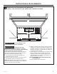
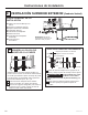
USE LA PLANTILLA DEL GABINETE
SUPERIOR PARA LA PREPARACIÓN
DEL GABINETE SUPERIOR
A2
RECIRCULACIÓN (Sin Conductos No Ventilados)
VISIÓN GENERAL DE LA
INSTALACIÓN
A1. ADHERA LA PLACA DE MONTAJE A LA
PARED
A2. USE LA PLANTILLA DEL GABINETE
SUPERIOR PARA LA PREPARACIÓN DEL
GABINETE SUPERIOR
A3. AJUSTE EL MOTOR DEL CALENTADOR
A4. CÓMO INSTALAR EL FILTRO DE CARBÓN
A5. MONTE EL HORNO MICROONDAS
A6. INSTALACIÓN/ REEMPLAZO DEL FILTRO DE
CARBÓN SIN ACCESO A LOS TORNILLOS
SUPERIORES Y LA UNIDAD YA FUE MONTADA
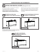
• Lea las instrucciones sobre la PLANTILLA DEL
GABINETE SUPERIOR.
• Pegue la misma debajo del gabinete superior.
• Haga los agujeros siguiendo las instrucciones en la
PLANTILLA DEL GABINETE SUPERIOR..
Use gafas de seguridad al
realizar agujeros en la parte
inferior del gabinete.
Es necesario hacer agujeros para los tornillos del
soporte superior y un agujero lo suficientemente
grande para que el cable de corriente lo pueda
atravesar.
A
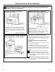
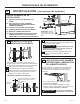
Coloque la placa de montaje contra la pared e
inserte las tuercas mariposa en los agujeros de la
pared para montar la placa.
PRECAUCIÓN
Tenga cuidado para evitar
pellizcos en los dedos entre la parte trasera de
la placa de montaje y la pared.
Ajuste todos los tornillos. Empuje la placa hacia
afuera de la pared para ayudar a ajustar los
tornillos.
3
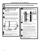
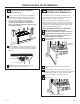
ADHERA LA PLACA DE
MONTAJE A LA PAREDL
A1
A
C
D
B
Adhiera la placa a la pared usando tornillos con
resortes. Por lo menos un tornillo de madera deberá
ser usado para adherir la placa al montaje de pared.
Retire las tuercas mariposa de los tornillos.
Inserte los tornillos en la placa de montaje a
través de los agujeros designados para entrar en
la placa de yeso y vuelva a ajustar las tuercas
mariposa a 3/4” sobre cada tornillo.
1
4
2
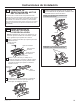
IMPORTANTE: NO retire
los espaciadores de cartón
entre el protector de calor y la
puerta.
Pared
Placa de
Montaje
Espacio para Tornillos con Resorte
Superior al Grosor de la Pared
Extremo del
Tornillo
Tornillo
con
Resorte
Tuercas mariposa
Para usar tornillos con resorte:
PRECAUCIÓN
CUT HOLE THROUGH REAR WALL FOR EXHAUST ADAPTOR
12"
4"
NOTE: IT IS VERY IMPORTANT TO
READ AND FOLLOW THE DIRECTIONS
IN THE INSTALLATION INSTRUCTIONS
BEFORE PROCEEDING WITH THIS
REAR WALL TEMPLATE.
This Rear Wall Template serves to position the bottom
mounting plate and to locate the horizontal exhaust
outlet.
1. Use a level to check that the template is positioned
accurately.
2. Locate and mark at least one stud on the left or
right side of the centerline.
NOTE:
It is important to use at least one wood
screw mounted firmly in a stud to support the weight
of the microwave. Mark two additional, evenly spaced
locations for the supplied toggle bolts.
3. Drill holes in the marked locations. Where there is
a stud, drill a 3/16" hole for wood screws. For holes
that do not line up with a stud, drill 5/8" holes for
toggle bolts.
NOTE::
DO NOT INSTALL THE MOUNTING PLATE
AT THIS TIME.
4. Remove the template from the rear wall.
5. Review the Installation Instruction book for your
installation situation.
Darle vuelta a la hoja para consultar la
versión en Español.
CAUTION - IF EXHAUST ADAPTOR IS POSITIONED OUTSIDE
RECOMMENDED DIMENSION, GREASE-LADEN AIR WILL
DISCHARGE INTO HOUSE STRUCTURE
30” MINIMUM WIDTH REQUIRED
REAR WALL TEMPLATE
F. CUT OUT FOR HORIZONTAL
OUTSIDE EXHAUST
Locate and mark holes to align with holes in the
mounting plate.
IMPORTANT:
LOCATE AT LEAST ONE STUD ON EITHER SIDE OF
THE CENTERLINE.
MARK THE LOCATION FOR 2 ADDITIONAL, EVENLY
SPACED TOGGLE BOLTS IN THE MOUNTING PLATE
AREA.
Trim the rear wall template along the dotted line.
3/8" TO EDGE
C
A
C
D
B
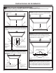
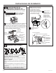
NOTES:
- 13” Max Cabinet Depth
- 15” deep cabinets require additional steps using
an additional installation kit: JX36BUMP
OPTION 1
OPTION 2
STEP 1:
Installer uses bracket to make 2 marks. First
mark is made by using the stampled slot in bracket.
Second mark is made on the ouside edge of bracket.
STEP 2:
Installer moves bracket to the other side of
the cabinets and makes 2 more marks. Marks are the
same as STEP 1, just opposite side.
STEP 4:
Make a mark here, along
inside bottom of the
stamped slot provided.
Make a mark
here,
even with
bottom of
stamped
slot
Make a mark here, along
inside bottom of the
stamped slot provided
(same as Step 1).
Make a
mark here,
even with
bottom of
stamped
slot
Horizontal line
A
C
D
B