LMU Users Guide Version 1.0.6 December 2009 V1.0.
LMU Users Guide Table of Contents Table of Contents ........................................................................................................................................ 1 1 Introduction ......................................................................................................................................... 5 1.1 About CalAmp – Who we are… ................................................................................................. 5 1.2 About CalAmp – What we do… ...
LMU Users Guide 6 7 8 9 5.2.2 MDT Mode ....................................................................................................................... 36 5.3 Using The Garmin NUVI or MacKenzie Labs DAD-A1214 .................................................... 40 5.4 Using the Modem Port .............................................................................................................. 41 5.4.1 Selecting a Modem Driver .................................................................
LMU Users Guide 9.5.1 Odometer Message .......................................................................................................... 65 9.5.2 Position Update Message ................................................................................................ 66 9.5.3 GPS Debug Output .......................................................................................................... 68 9.6 Over-The Air Real-Time GPS Updates .............................................................
LMU Users Guide 14 LMU Programming Examples ........................................................................................................105 14.1 LMU Programming – Delivery Fleet .......................................................................................106 14.1.1 Project Overview ............................................................................................................106 14.1.2 Project Proposal ......................................................................
LMU Users Guide 1 Introduction 1.1 About CalAmp – Who we are… Founded in 1981, CalAmp stands at the forefront of technology evolution as a result of strategic collaborations with forward thinking customers. By anticipating technology and industry trends, we rapidly develop cutting-edge solutions to help our customers effectively realize time and cost savings.
LMU Users Guide 2 CalAmp LMU – Hardware Overview In today's competitive market place, many companies rely on telemetrics in their business to remove or minimize the risks associated with vehicle investment, improving efficiency, productivity and reducing their overall transportation costs. CalAmp products offer easy solutions to a wide range of markets.
LMU Users Guide 3 LMU Setup – Configuration Overview This section describes how the LMUs store their configuration data and how they are programmed. The meaning of each parameter will be touched upon in the sections that follow. A complete listing of parameters and S-registers can be found in Appendix A and B respectively. 3.1 Parameters 3.1.1 What are Parameters? Parameters are how the LMU stores any of its configuration items thus; any setting that can be changed is contained within a Parameter.
LMU Users Guide Parameters. The LM Direct™ Parameter Message is described in the LM Direct™ Reference Guide. The SMS Parameter Message is described later in this document. 3.1.2.1 AT Commands The AT$APP PARAM commands can be used to query or set Parameter Values. The set command generally looks like: AT$APP PARAM , , It should be noted that there can be more than one field depending on the Parameter’s definition. Each sub-Value is separated by a comma.
LMU Users Guide The LMU does support several other AT Commands beyond the Parameter commands. The most common ones are mentioned through-out this document. A terminal program such as HyperTerminal is generally used to issue AT Commands to the LMU. Please refer to Appendix D for instructions on establishing a connection. 3.1.2.2 Parameter Messages Parameter Messages are a means of remotely changing the parameter values of an LMU remotely.
LMU Users Guide S-Registers start at S-120 and end at S-171. For the Parameter commands (or messages) this corresponds to an Index range of 0 to 51. That is, the Index of an S-Register is the SRegister number minus 120. 3.3 Parameter Masking 3.3.1 What is Parameter Masking? Parameter masking is a means of programming select parts of a Parameter’s Value. This only applies to Parameter Values that are bit mapped.
LMU Users Guide 4 Working with Inputs, Outputs and Power 4.1 I/O Introduction The CalAmp LMU products offer a variety of inputs and outputs to enable a wide variety of vehicle and asset tracking applications. For a complete description of what types of inputs and outputs are supported by a given device, please refer to its installation guide. 4.2 Input Types The LMU products offer the following input types. Please note that not all inputs are supported by all products. 4.2.
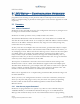
LMU Users Guide Figure 1 - Sample Digital Input Wiring V1.0.
LMU Users Guide 4.2.1.1 Changing the Input Bias For some LMU products, the input Bias can be controlled by S-Register 158 (or Parameter 1024, Index 38). Each bit of this register is assigned to a specific input. If the associated bit is set, then the input is biased high, if the bit is cleared, then the input is biased low.
LMU Users Guide 4.2.5 High Temperature Input The LMU-1100 and LMU-1200 have a built in high temperature threshold of 60 °C. If the internal temperature of the LMU is above this value, then the input will be in the High state. If the LMU’s temperature is below this value, then the input will be in the Low state. 4.2.6 The 1 Bit Bus The 1-Bit-Bus allows the LMU-4100™ and LMU-2500™ to be connected to a variety of 1Wire® Devices.
LMU Users Guide Enable Temperature Sensors: AT$APP PARAM 1024,51,64,64 Enable ID Tag AT$APP PARAM 1024,51,64,0 The LMU-2500™ can work with up to eight (reference 0-7) Maxim DS28EA00 1-wire temperature sensors in a chain configuration interconnected by a 3-wire bus. Upon boot-up, the LMU executes a discovery procedure to detect the number of connected DS28EA00 devices.
LMU Users Guide 4.3 Output Types 4.3.1 Relay Outputs The LMU’s outputs are designed to drive external relays. These outputs provide a highcurrent, open-collector driver that can sink up to 150 mA each. These drivers may be used to drive external relays that can then control vehicle functions such as door locks, fuel shut-off valves, sirens and lights. If additional current is required to drive the relays, external circuitry can be added to source the current.
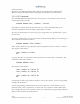
LMU Users Guide Key Switch Cut wire BLUE GREEN LMU-1000 Starter Relay Figure 4 - LMU-1000™ Vehicle Disable Feature Using the above set-up a vehicle can be enabled or disabled by clearing (enabled) or setting (disabled) output 0 via PEG Scripts, Real-Time PEG Actions or SMS messages. 4.3.2 External vs. Internal Power Switch This output allows the LMU to switch between power sources when certain conditions are met (e.g. low power on the currently selected supply).
LMU Users Guide 4.4 Selecting the GPIO Function The input or output functionality of the GPIO pins is controlled by S-Register 159. Like the input bias controls, each bit is associated with a different GPIO. If the bit is set, then the GPIO will act as an output. If the bit is cleared, the GPIO will act as an input.
LMU Users Guide 4.5 Working with Sleep Mode 4.5.1 Configuring the Input Wake-Up Monitor The LMU’s digital inputs have an additional feature besides simple On/Off detection which is to wake the LMU out of its sleep mode. The LMU is capable of filtering which input(s) can wake it from sleep based on Parameter 1029. Like S-Registers 157 and 158, each bit of Parameter 1029 is associated with a specific input.
LMU Users Guide 4.5.2 Keeping the Expansion Port powered during sleep The expansion port is the 16 pin connection on the back of the LMU where peripheral devices are plugged in. This port can actually remain powered while the LMU is sleeping.
LMU Users Guide 4.6 Working with the Status LEDs By default, the Status LEDs work as described in the Install Guides, however, it is possible to override the default behaviors on the LMU-2500 and LMU-4100. Specifically, the Comm LED can be over-ridden to report Input Status for inputs 0-4 and the GPS LED can be over-ridden to provide satellite information. 4.6.1 Input State and Satellite Count Mode In this mode, the Comm LED (Orange) will alternate between Comm Status and Input Status every 5s.
LMU Users Guide For the GPS LED (Yellow) the GPS LED will indicate OFF (LED off), ON (slow blink) and TIME-SYNC (fast blink) as it always has. When the GPS is acquired, it reports the number of satellites being tracked by going on for 500mS, off for 500mS and then for each satellite being tracked, on for 125mS and off for 125 mS. After 5-sec, the pattern repeats.
LMU Users Guide For example, let us assume that all inputs are biased low. If Ignition is On, and Inputs 2 and 4 are high then the COMM LED will blink twice, followed by a pause, followed by 4 more blinks. This mode is enabled by setting both Bits 3 and 5 of S-Register 171. To enable this mode, you would use: AT$APP PARAM 1024,51,40,40 To return the LEDs to their normal behavior, you would use: AT$APP PARAM 1024,51,40,0 4.6.
LMU Users Guide 4.7 Restoring values through a power cycle The LMU is capable of storing some of its values to non-volatile memory so that they can be restored after a power cycle.
LMU Users Guide Do no save on a soft reset: AT$APP PARAM 1024,7,64,0 Save on ignition off AT$APP PARAM 1024,7,128,128 V1.0.
LMU Users Guide 5 Working with External Serial Devices While all of the LMU products have a host port to allow users to issue AT Commands to configure, debug and control the device, only the LMU-4100 supports external serial devices as a peripheral. The one exception is that the LMU-2500 does support the output of NMEA sentences on its host port. The CalAmp LMU-4100™ and LMU-2500™ supports three external serial ports for use with other devices, though only two can be available at the same time.
LMU Users Guide 5.1 Using the Host Port The Host Port of the LMU-4100™ and LMU-2500™ can be accessed in one of two ways, either in Host mode, which is meant for use with laptops, and PDAs or MDT mode, which is meant for use with serial mobile data terminals, bar-code readers, magnetic-card readers and other ‘dumb’ serial devices. In Host mode, a host device can issue AT Commands, receive NMEA data or establish a Dial-Up Networking session.
LMU Users Guide DO NOT use values that are not on this list as it may cause unexpected behaviors within the LMU. Changing the BAUD rate setting will have an effect on the NMEA output and the Dial-Up Networking functions of the Host Port. 5.1.2 Host Mode – NMEA Output NMEA messages are generally used by in-vehicle navigation applications to plot the current position of the vehicle and compute real-time driving directions.
LMU Users Guide AT$APP PARAM 1024,8,1,1 Turn on RMC AT$APP PARAM 1024,8,16,16 5.1.3 Host Mode – Dial-Up Networking The LMU-4100’s™ Host Port can be used by a laptop or PDA to establish a Dial-Up Networking session. This is to allow the laptop or PDA access to the Internet to enable such applications as email and web-browsing. There are two basic steps to accomplish this: 1. Install a modem driver 2.
LMU Users Guide To re-enable KMIP polling you would use: ATS153=10 KMIP Polling is described in detail later in this document. 5.1.3.3 Bypass Mode Bypass mode, in reference to Dial-Up Networking applies to just the CDMA LMU-4100™. In this mode, the LMU switches itself out of the data path and allows the host laptop or PDA to establish the Dial-Up Networking session directly with the CDMA modem. This occurs automatically when the Host Port BAUD rate and the Modem Port BAUD rate are set to the same value.
LMU Users Guide 5.1.4 MDT Mode MDT Mode allows a dumb serial device to pass messages through the LMU-4100™ or the LMU-2500™ to the back-end system using LM Direct User Messages. The backend system may also send a User Message to the LMU, the contents of which should be forwarded to the serial device. MDT mode can be enabled on either the Serial Adapter peripheral or on the ioPOD peripheral by means of a jumper. The Host Port’s MDT mode settings are controlled by S-Registers 130 thru 138 and SRegister 141.
LMU Users Guide To disable this mode, you would use: ATS130=0 5.1.4.3 MDT Mode – Serial Port settings The MDT Mode serial port settings are independent from the Host Port Host Mode settings. The MDT mode settings are controlled by 2 S-Registers, 131 and 132. These register control the BAUD Rate, Data Bits, Parity and Stop Bits settings for MDT mode. These changes do not affect the settings of S-148 or the +IPR command (i.e. the host port baud rate).
LMU Users Guide 5.1.4.4 MDT Mode – Termination Character The LMU-4100™ and LMU-2500™ can optionally detect a ‘Termination Character’ in the data sent from the serial device over the MDT port. This character is meant to denote the end of the message and that LMU should send the contents to the back-end system. The Termination Character is meant for use when the serial device is sending ASCII encoded text. When using serial devices that produce binary messages, it is best not to use a Termination Character.
LMU Users Guide back-end system. Please note that the LMU will still obey its maximum buffer size (804 bytes) even if the Termination Length is undefined. The Termination Timeout is controlled by S-Register 138 and ranges from 1 to 255ms. For instance, to set the timeout for 120ms you would use: ATS138=120 Like the Termination Length, setting S-register 138 to 0 will disable the Termination Timeout feature. 5.1.4.7 MDT Mode – User Message ID The User Message ID field serves two purposes for User Messages.
LMU Users Guide The message disposition is controlled by S-Register 137. The settings are as follows: • • • • • • 1 or 2 = Send Message, Log if Send Fails 3 = Log Message 4 = Priority Message 5 = Unacknowledged Message 7 = Route Incoming (Client to LMU) SMS messages to the host serial port. Route all User Messages to the SMS Destination Address 8 = Route Incoming (Client to LMU) SMS messages to the host serial port. Route all User Messages to the last phone number that sent the LMU a message 5.1.4.
LMU Users Guide 5.2 Using the Aux Port The Aux Port on the ioPOD can be used for one of two purposes, it can either be a source for NMEA messages, or it can act as an MDT port. The mode of the Aux Port is controlled by S-Register 160. If bit 0 of this register is cleared, then the port is setup for MDT mode. If bit 0 is set, then the port is set up for NMEA mode (bit 0 is set). For MDT mode you would use: AT$APP PARAM 1024,40,1,0 For NMEA mode you would use: AT$APP PARAM 1024,40,1,1 5.2.
LMU Users Guide • 115200 BAUD (ATS161=12) To change the Data Bits, Parity and Stop Bit settings, you would use S-Register 162. The follow table describes each of the available combinations: Data Bits 8 8 8 8 8 8 7 7 7 7 7 7 6 6 6 6 6 6 5 5 5 5 5 5 Parity None None Even Even Odd Odd None None Even Even Odd Odd None None Even Even Odd Odd None None Even Even Odd Odd Stop Bits 2 1 2 1 2 1 2 1 2 1 2 1 2 1 2 1 2 1 2 1 2 1 2 1 S-162 Setting 7 3 31 27 15 11 6 4 30 26 14 10 5 1 29 25 13 9 4 0 28 24 12 8 5.2.2.
LMU Users Guide 5.2.2.3 MDT Mode – Message Termination Length The Message Termination Length for the Aux port is defined by S-Register 165. The value of S-165 indicates how many bytes to make the message. The value may range from 1 to 201 giving a byte range of 4 to 804 bytes. For instance, to set a Message Termination Length of 200 bytes you would use: ATS165=50 Setting the value of S-165 to 0 disables the Termination Length feature. 5.2.2.
LMU Users Guide • Attempt to send the User Message. If the message cannot be sent, or the log is already active, the User Message is logged. • Immediately log the User Message • Route the User Message (contents only) to the SMS Destination Address • Route the User Message (contents only) to the last phone number of an incoming SMS message With the last two options the contents of any incoming SMS messages will be routed to the serial device. The Message Disposition is controlled by S-Register 167.
LMU Users Guide 5.3 Using The Garmin NUVI or MacKenzie Labs DAD-A1214 The LMU-4100 also supports messaging for two specific serial devices, the Garmin NUVI and the MacKenzie Labs DAD-A1214. For which messages are supported for each device, please refer to the PEG Programming Guide. Both the device selection and which port the device is connected to are dictated by SRegister 173. The lower 4 bits dictate the device and the upper 4 bits dictate the destination port.
LMU Users Guide 5.4 Using the Modem Port An external Modem Port is only available when using the TetheredLocator adapter. Otherwise, the Modem Port is assumed to be connected to the LMU’s internal modem. Using the external Modem Port allows users to connect an LMU to an existing modem or phone via a serial connection. The LMU should then be able to use the phone or modem’s Dial-Up Networking capabilities to establish a data session.
LMU Users Guide The first value indicates what the S-120 setting should be. For example to use a generic CDMA modem driver you would use: ATS120=140 If you are unsure of what driver you should use for your external device, pick the generic one (ATS120 = 128) as it can be adapted to most network technologies. 5.4.2 Configuring the Modem Port’s BAUD Rate Like the Host Port, the Modem Port only allows users to change the BAUD rate settings.
LMU Users Guide 5.4.4 Setting the network username and password For some networks, the operator may require that a username and password be supplied before the device is allowed to establish a data session with the network. The LMU can be programmed to supply these values as part of the Dial-Up Networking negotiations. The username is controlled by Parameter 2314 and the password is contained in Parameter 2315.
LMU Users Guide 6 Using the CalAmp Bluetooth Adapter (BTA) The LMU-4100™ supports Bluetooth functionality using the CalAmp Bluetooth Adapter (BTA) (Part Number TC1106-9). The LMU-4100™ can be configured to use the BTA as its Host port able to either initiate or accept the Bluetooth connection to the other device(s). The Bluetooth adapter has three parameters associated with it. • Parameter 2080 – Bluetooth Name: This Parameter contains a string which is compared to the remote device names during a scan.
LMU Users Guide Setting bit 5 will place the BTA in low security mode, clearing it will use high security mode. 6.1 Using the BTA as the Host Port When acting as a host port, the LMU-4100™ and newer BTA will actually present three ports: • • • Port 1 which is used for NMEA output using a Serial Port Profile Port 2 which is used as the primary Serial Port Profile or Dial-Up Networking profile Port 3 which is used for AT Commands and Debug output.
LMU Users Guide Again, we do not need to worry about the profile or BAUD rate settings. When you pair to the BTA, be sure to select the Debug port (or last serial port profile) to connect to this function. Please note that this function may not be available on all connecting devices. 6.1.3 Dial-Up Networking – Dial-Up Networking Profile The newer BTAs support a separate Dial-Up Networking port for use with the Dial-Up Networking profile.
LMU Users Guide 7 Working with Comm Comm. refers to any features of the LMU that have something to do with the behavior of its wireless modem. This section is intended to cover the Comm related features not discussed in the Activating the CalAmp LMU sections found in the LMU Installation Guides. 7.1 Using a second Comm profile The Comm profile is the set of parameters the LMU needs to access the wireless network.
LMU Users Guide Up to two Contexts can be defined. The first Context is stored in index 0 of parameter 2306, the second is stored in index 1. Which Context the LMU will initially use is controlled by the GPRS Context – Current Index Parameter (2307). If the value of this Parameter is 0, the LMU will start with the first Context, if the value is 1 it will start with the second.
LMU Users Guide 7.3.2 Log activity restart This feature is similar to the Send Fail Restart, only it is time based instead of packet delivery based. In this case, the LMU will reset the wireless modem if the LMU’s log space has been active for a specific period of time. This period is defined by S-Register 157 and is stored in minutes. This timer starts when the LMU’s log goes active and reset when it empties.
LMU Users Guide The master enable/disable setting is controlled by bit 3 of S-Register 154. Setting this bit will disable the Connection Monitor, clearing it will enable monitoring. To enable the Monitor you would use: AT$APP PARAM 1024,34,8,0 To disable it, you would use: AT$APP PARAM 1024,34,8,8 When using the LMU to establish a Dial-Up Networking session with a laptop or PDA, it is best to disable the Connection Monitor. 7.3.
LMU Users Guide If the LMU is set to Require a given network it must connect to that network before a data session will be established. If the data session is already established and the modem roams off the Required network, the LMU will automatically drop the data session and attempt to reconnect to the Required network.
LMU Users Guide 7.5.1 GPRS networks The GPRS LMU-4100 supports all three options: Require, Prefer and Exclude.
LMU Users Guide 7.6 Controlling the Data Session For the most part the data session of the LMU is controlled by PEG. The one exception to this is the Power On or Wake-Up behavior. On a Power Up or a Wake-Up the LMU will immediately 7 attempt to establish a data session. This behavior can actually be prevented using bit 7 of S-Register 140. If you set this bit, then the data session will not be attempted on Power Up or Wake Up. If it is cleared, then the LMU will behave as normal.
LMU Users Guide 7.8 Back Off Algorithms Both the CDMA and GSM LMUs make use of a back-off algorithm when they encounter problems connecting to the wireless network (e.g. registration denied, MIP errors, etc…). For the GSM LMUs if registration is denied (CREG=3), the modem will be restarted and the registration wait delay will be increased by the delay schedule. The normal delay is 300 seconds.
LMU Users Guide 8 Controlling LMU Access The LMU has a variety of security features that will limit access to various functions within the LMU. It is very important that you do not change any of the default settings for these features until you fully understand the implications of doing so. 8.1 Service Enables The Service Enables Parameter allows a user to enable or disable various features of the LMU.
LMU Users Guide AT$APP PARAM 1025,0,1,1 The corresponding disable commands would be: TAIP Interface: AT$APP PARAM 1025,0,8,0 Inbound Messaging: AT$APP PARAM 1025,0,4,0 Event Reporting: AT$APP PARAM 1025,0,2,0 PEG Processing: AT$APP PARAM 1025,0,1,0 8.2 Access IP Address List When the LMU receives a UDP packet 8 it compares the source IP address with those contained in its Access IP Address list. If the LMU finds a match, then the LMU will process and, if needed, respond to the incoming packet.
LMU Users Guide The current IP address for PULS is 207.71.209.248. For this example, the IP range used by your office is 166.143.185.65 thru 166.143.185.90 and the IP range used by your data hosting facility is 172.90.80.240 thru 172.90.81.50 10. To set up an appropriate access list you would use the following commands: PULS: AT$APP PARAM 1281,3,207.71.209.248 Office: AT$APP PARAM 1281,2,166.143.185.255 Data Center: AT$APP PARAM 1281,1,172.90.255.
LMU Users Guide To set up an appropriate Host Access List you would use the following commands: AT$APP PARAM 1282,0,166.143.185.255 AT$APP PARAM 1282,1,172.90.255.255 In this case you should notice two differences from above, first is that we started with Index 0 since this is where the default value sits. The second this is that we didn’t need to put PULS’s IP address in the list. 8.4 Primary Port Password The last security feature of the LMU is the Primary Port Password.
LMU Users Guide Because the password is stored in a Short Text String it is limited to 15 alpha numeric ASCII characters. To enable this feature you would use: AT$APP PARAM 1024,51,16,16 To disable this feature you would us: AT$APP PARAM 1024,51,16,0 Be aware that this password also applies to AT Commands sent via SMS. To remotely unlock an LMU via SMS you would use a variant of the !R0 SMS message.
LMU Users Guide 9 Working with GPS Obviously one of the most important pieces of the LMU is the GPS Receiver. This section describes the supporting features that exist outside of PEG which can affect the behavior of the GPS Receiver. 9.1 NMEA Messaging One of the more common uses of a GPS Receiver is to feed NMEA data into a real-time mapping application that is running on a laptop or PDA. The LMU’s support of this feature is described in the Working with Serial Devices section. 9.
LMU Users Guide 9.2.3 GPS Restart In some cases it may be desirable to have the LMU automatically reset the GPS Receiver outside of the PEG script. This timer, which is controlled by S-Register 144, is the length of time the LMU will wait after losing GPS signal before resetting the GPS Receiver. The value of this Register ranges from 1 to 255 minutes with a value of 0 disabling the reset. It is VERY important that this value be long enough to allow the LMU to gain GPS lock.
LMU Users Guide 9.3.3 GPS Accuracy Threshold The GPS receiver produces a Horizontal Accuracy Estimate for each position it produces. The LMU uses this estimate to decide if it should update its position when Pinning. This estimate threshold is controlled by S-Register 142. If the new position of the GPS Receiver has an estimate lower than the value in S-142 then the LMU will allow its position to be updated, otherwise the new position is ignored. The value of S-142 is in meters.
LMU Users Guide It is very important to note that the NMEA data produced by the LMU is not subject to Pinning, therefore the position reported in a real-time mapping application may differ from the position reported via LM Direct, or SMS. 9.4 Special Functions 9.4.1 Receiver Mode The GPS receiver supports a number of ‘modes’ for tracking. The Receiver Mode controls the GPS receiver’s internal filters. The looser the setting (i.e. High Dynamic Aircraft) the noisier the position will be.
LMU Users Guide 15° filter is enabled by setting bit 5 of S-Register 139. The 5° filter is enabled by clearing bit 5 of S-Register 139. To enable the 15° filter you would use: AT$APP PARAM 1024,19,32,32 To enable the 5° filter you would use: AT$APP PARAM 1024,19,32,0 In general it is best to use the 5° filter for high dynamic applications (e.g. Automotive and above) and the 15° filter for low dynamic applications (e.g. pedestrian or stationary) 9.4.
LMU Users Guide AT$APP PARAM 1024,19,128,0 9.5 Local GPS Messaging While connected to the LMU’s host port, it is possible to enable further GPS messaging beyond or instead of NMEA. Two of these messages are intended for use with MDTs while the other is used for GPS debug. 9.5.1 Odometer Message The ODO message is meant for use with MDTs to provide a compact description of the current position of the LMU including an odometer estimate.
LMU Users Guide This is the maximum speed the GPS Receiver has produced since the LMU was powered up. This value is in centimeters per second This value is an ‘as the crow files’ distance value computed between two GPS positions. This computation occurs when the LMU regains GPS signal after losing it for more than 1 second. This value is in meters. This is the overall distance the LMU has travelled since power up. The value is displayed in meters.
LMU Users Guide This value is the Action Modifier associated with the Display Position PEG Action. If the POS message is produced automatically (i.e. not through PEG), this value will be 0.
LMU Users Guide Unlike the ODO message, general debug does not need to be enabled. 9.5.3 GPS Debug Output GPS Debug Output enables a variety of debug messaging the LMU receives from its GPS receiver. This messaging should only be enabled when requested by a member of CalAmp’s support team. It is enabled by setting bit 2 of S-Register 126 and enabling general debug. That is: AT$APP PARAM 1024,6,4,4 ATS125=3 (or ATS125=7) It is disabled by clearing bit 2 or turning off general debug.
LMU Users Guide 10 CalAmp LMU Interface – LM Direct The primary interface to the LMU once it is in the field is LM Direct. LM Direct is a UDP/IP based protocol that allows you to: • • • • Receive location data from the LMU based on the PEG Script Request location and status data from the LMU based on Unit Request messages Send and Receive User Messages to/from host serial devices Make configuration changes to various LMU parameters.
LMU Users Guide The DNS look-up occurs every time the LMU successfully connects to the network or 15s after a Parameter update. The initial configuration of the LMU’s Inbound settings is generally handled by AT Command. The first step is to program the Inbound IP address and Port using: AT$APP INBOUND The second step is to program the Inbound URL: AT$APP Param 2319,0,”” It is very important that you program the URL as well as the Inbound IP address and Port.
LMU Users Guide empty its log using a SEND LOG Action or a message using the Store and Forward mechanism is introduced. In PEG, an Action using just LOG operates in batch mode. • Unacknowledged: Unacknowledged messages are ones that are never logged. The LMU attempts to send the data if the network is available. Once the send has been completed, the message is erased. If the network is not available, then the message is immediately deleted.
LMU Users Guide a log retry interval expires. If the log successfully empties, the Retry Schedule is halted and reset. If not, the LMU will wait for the next retry attempt. When the Log Retry Schedule expires, then the LMU will only attempt to deliver data when a new record is introduced into the log, or if the LMU establishes a new data session with the wireless network. The Log Retry Schedule is based on the state of the LMU’s ignition sense.
LMU Users Guide appropriate acknowledgement) or it reaches the bottom of its Inbound list. Upon reaching the bottom, the LMU will wrap back to the top of the list and try again. The selection of the next IP address will occur when the Inbound Retry Schedule expires or when the Log Retry Schedule expires. The LMU provides several modes to handle which inbound address is used. 10.2.4.
LMU Users Guide 10.2.4.4 Fixed Inbound Address Index When in Fixed Inbound Address mode, the LMU-2500 or LMU-4100 will not change its Inbound IP address based on a send failure. To enable this mode, Bit 6 of Parameter 1280 must be set. The only time the inbound address will change is on a Comm Select PEG Action. AT$APP PARAM 1280,0,64,64 Please note that the Fixed Inbound setting will over-ride the Dynamic, Static and Random Inbound modes.
LMU Users Guide 10.3 Maintenance Settings The Maintenance settings of the LMU are used to communicate with the PULS system. They define what IP address and port the Maintenance data should be sent to. They also define how often the Maintenance Message should be created. The Maintenance Message is the LM Direct ID Report and thus does not contain any location data about the particular LMU. 10.3.
LMU Users Guide Message Interval in Parameter 2313. Keep in mind use of the Null Message may have noticeable impacts on you data usage if the interval is set to an extremely low value. The Null Message Interval can range from 1 to 65535s. A value of 0 disables the Null Message. For example, to set a 2 minute Null Message Interval you would use: AT$APP PARAM 2313,0,120 If another LM Direct message is sent before the Null Message Interval expires, the Interval is reset.
LMU Users Guide 11 CalAmp LMU Interface – SMS Short Message Service (SMS) is a communications protocol allowing the interchange of short text messages between mobile telephone devices. SMS is supported on all CalAmp devices except the iDEN LMU-4100™. SMS is generally used as an alternative or as an augmentation to LM Direct.
LMU Users Guide 11.1.1 SMS Event Report The SMS Event Report is much like the LM Direct Event Report in that it is meant to contain a useful set of location and unit status data. It should be noted that the SMS Event Report will contain less data than the LM Direct Event Report due to message size limitations of the SMS protocol. The message format is as follows: !E<78omm.
LMU Users Guide •
LMU Users Guide • (1 byte) The current state of the inputs, bit mapped as follows: Bit 0 – Ignition Bit 1 – Input 1 Bit 2 – Input 2 Bit 3 – Input 3 Bit 4 – input 4 Bit 5 – Input 5 Bit 6 – input 6 Bit 7 – Input 7 • (1 byte) Status of key modules within the unit.
LMU Users Guide 11.1.2 SMS Text Status Message The Text Status message was designed to help installers or support personnel to easily determine the state of an LMU using SMS. The message contains several key status indicators including Comm Status, GPS Status, Inbound Address and input states. Its format is as follows: APP: COM: [./d/D][./a/A][.
LMU Users Guide valid data session. This field will contain the current IP address of the LMU as assigned by the wireless network. Note that if you see a value of 192.168.0.0, this is an indication that the LMU has not been able to establish a data session. o [] The current Access Point Name in use by a GSM LMU. • GPS: o [Antenna ]: This field, if present, indicates a problem with the LMU’s GPS antenna. A value of Short indicates that the antenna cable has likely been crushed.
LMU Users Guide This value should match UDP port you are using on your LM Direct server. It is typically 20500. o : This is the current UDP/IP messaging protocol in use by the LMU. In general it should be LMD. V1.0.
LMU Users Guide 11.1.3 SMS Text Message The SMS Test Message feature is a subset of PEG’s Short and Long Test Message features. The SMS Text Message therefore also comes in two varieties, a short message, that is 1-15 characters long and a long message that can be 1-63 characters long. The SMS Text Messages will have the following format: [],[][][] • • • • • : This is the short or long text message to be sent.
LMU Users Guide 11.1.4 SMS GPS Status Message The GPS Status Message allows users to remotely poll the LMU for its current position via SMS. The message is formatted as follows: GPS: LAT: LON: HDG: SPD: , MID: • • • • • • GPS: o [ ]: If these fields are present it indicates that the LMU has, or had a valid GPS solution.
LMU Users Guide 11.1.5 SMS Comm Status Message The Comm Status Message allows users to remotely poll the LMU for its current wireless modem status and settings via SMS. The message is formatted as follows: [./d/D][./a/A][./L] M:[O/C/E][./s][./r] I:[O/C/E][./s][./r] O:[O/C/E][./s][./r] • o : This is the signal strength the wireless modem sees from the network.
LMU Users Guide o [./S] This field indicates if the LMU has sent data thru the referenced socket. An ‘S’ indicates data has been sent. A ‘.’ indicates no data has been sent. o [./R] This field indicates if the LMU has received data thru the referenced socket. An ‘R’ indicates data has been received. A ‘.’ indicates no data has been received. o : The current URL associated with the referenced socket. Please note that the URL is truncated to 18 characters in length.
LMU Users Guide 11.2 SMS Request Messages There are two formal types of request messages than can be sent to an LMU and one informal type. The formal types, which are Unit Requests and Parameter Requests messages, generally elicit an SMS response from the LMU. The informal type, AT Commands, does not. The formatting and use of each is detailed in the following sections. 11.2.1 Unit Request Messages The Unit Request messages are designed to produce specific responses or actions from an LMU.
LMU Users Guide This request only applies to the LMU-1000. It will cause the LMU-1000 to initiate a software update from a server via HTTP. The is the 3-character version designation of the software to be downloaded (e.g. 12a). The LMU software should combine this version with the current App ID to build a file name for the update it is seeking to download. The format for the filename is: LMU__.jar (i.e. ‘LMU_086_12a.jar’).
LMU Users Guide 2=Read Response 3=Write Response 255=Error • This field will be the list of parameters needed to comply with the . This field can be of variable length and is ASCII-Hex encoded. The exact format will match the contents of the LM Direct Parameter message starting below the action byte. Please refer to the LM Direct Reference Guide for details. 11.2.
LMU Users Guide 12 CalAmp LMU Interface – TAIP The Trimble ASCII Interface Protocol (TAIP) is a Trimble-specified digital communication interface based on printable ASCII characters. TAIP was designed specifically for vehicle tracking applications using the Trimble asset tracking products. It has, however, been expanded upon by several companies to meet the needs of their specific devices. The CalAmp LMU-4100 is included among these devices. TAIP supports both scheduled and polled responses.
LMU Users Guide data string is comprised of any printable ASCII characters with the exception of the ‘>’, ‘<’, and ‘;’ characters which are used as delimiters. Field separators, including commas and spaces, are not part of the messages unless otherwise specified. Strings generally use fixed-length fields although some sentences use comma or semicolon delimiters. The message qualifier and the message identifier determine the format and length of the data string. • ; Field Separator.
LMU Users Guide ±EEEFFFFFFF Dec Deg ±GGGGGGHH Feet IIIJ ±KKKL MMMN OO PP QQ RRRRRRRRRR S MPH MPH Deg NA NA NA NA NA T NA 90.0000000 000.0000000 – 180.0000000 000000.00 – 999999.99 000.0 – 999.9 000.0 – 999.9 000.0 – 359.
LMU Users Guide distinguish which unit is reporting. If the Vehicle ID is included, it is delimited with a semicolon. ;ID=AAAA The default setting is: ID set to “0000” To include the vehicle ID in a TAIP sentence, you would use the TAIP Enables parameter (2048). Bit 1 controls the presence of the Vehicle ID. If this bit is set, then the ID is included. If it is cleared, it is omitted. The Vehicle ID is controlled by Parameter 2050.
LMU Users Guide To omit the event code you would use: AT$APP PARAM 2048,0,64,0 12.1.5.3 Input States TAIP sentences may include an optional Input State extension, the format of which is: IN=XXX The value of XXX may range from 0 – 255. Each bit of XXX represents a different input. If the bit is set, the input is in the high state, if it is cleared, the input is in the low state.
LMU Users Guide 12.1.5.5 Checksum Checksums are useful in detecting data transmission errors when the communication channel is noisy. If provided, they are delimited from the rest of the sentence by a semicolon and are always the last element of the sentence before the end delimiter. ;*AA< The default mode of operation is to include checksums in sentences from the module. The checksum itself is a two-byte ASCII representation of an eight-bit hexadecimal value.
LMU Users Guide • • • Bit 0 = Enable / Disable the PV sentence Bit 1 = Enable / Disable the LN sentence Bit 2 = Enable / Disable the IO sentence. For example, to turn on all three messages you would use: AT$APP PARAM 2049,0,7,7 To turn off just the LN message you would use: AT$APP PARAM 2049,0,2,0 Note that the query (Q), frequency (F) and distance (D) qualifiers may be used with any of the message types regardless of the settings of this Parameter. 12.2.
LMU Users Guide Parameters 263 and 262 respectively (i.e. the Time-Distance Distance and Time-Distance Time Parameters). Receipt of ‘F’ and ‘D’ qualifiers will also automatically start TimeDistance profile 0. It is important to remember that this will override any existing PEG Time-Distance activities. Conversely, any subsequent PEG Time-Distance activities will override the TAIP ‘D’ or ‘F’ settings.
LMU Users Guide To disable it, you would use: AT$APP PARAM 2049,0,64,0 V1.0.
LMU Users Guide 13 LMU Maintenance 13.1 Mobile ID The Mobile ID is intended to be a unique identifier that would allow a remote application to identify which LMU sent an incoming message The Mobile ID is contained within the options header of an LM Direct message and is normally tagged on each message created by the LMU. Users have several options on what value can be used for the Mobile ID. They are as follows: • • • • • • The serial number of the LMU (i.e.
LMU Users Guide AT$APP Param 2304,0, To program in a phone number, you would use: AT$APP PARAM 2305,0, Both the user defined Mobile ID and phone number fields must be all digits. That is, they cannot contain spaces, brackets or dashes. The default setting is to have the ESN as the Mobile ID. 13.2 Firmware Versioning The firmware version of an LMU is broken into two parts, an application ID and the actual firmware revision.
LMU Users Guide 13.4 Downloading Firmware In some cases it may be necessary to upgrade the firmware of an LMU. The two main reasons for performing a firmware upgrade are the addition of a new feature or a bug fix. This section details how firmware updates can be performed on an LMU. 13.5 Downloading Firmware – Locally Local firmware downloads are done from a laptop connected serially to the LMU. It is recommended that firmware upgrades be performed via a wired connection (i.e.
LMU Users Guide 5. Click the Send button. This should bring up a progress window. DO NOT close this window until the download has completed. 6. The following message should appear in the HyperTerminal window when the download completes: Transfer Completed Successfully! -------------------------------Name: LMU_GSM_81_80b.bin Size: 239824 Bytes -------------------------------13.5.
LMU Users Guide 13.6 Downloading Firmware – Remotely Remote firmware downloads for the LMU products are managed by the PULS™ system. Please refer to the PULS Users Guide for details. 13.6.1 Remote Firmware Upgrade – LMU 1000™ The LMU-1000™ can be forced to do a remote firmware upgrade by use of an SMS Message.
LMU Users Guide 14 LMU Programming Examples In this section we detail out three examples solutions using the LMU. Keep in mind that these are fictitious scenarios designed to highlight certain features of the LMU. In the examples, will be referring to the city of Hagensville in the state of Hagen. Hagensville is not modeled after anywhere in particular, but it does have the unique feature of housing all the services we wish to demonstrate. It is also in a country where the metric system is used.
LMU Users Guide 14.1 LMU Programming – Delivery Fleet 14.1.1 Project Overview Hagensville Express Delivery is the leading local courier service; however they have started to experience some loss of business due to larger competitors. They are looking to make improvements to their services specifically focusing on vehicle and driver efficiency. This will include route optimization, in-vehicle driving directions, and the addition of real-time dispatch.
LMU Users Guide 14.1.2.2 Local Application Requirements We are going to host the Local Application on the handheld mobile computer we selected above. Since the device is Windows Mobile™ based so we have a variety of off the shelf software to choose from. Specifically we elect to purchase the In-Vehicle Navigation Software. We decide to build the bar-code scanner and dispatch messaging piece ourselves.
LMU Users Guide For this example, the data will be in the LM Direct format 21 which will be sent to your production server and, on the peripheral front, we will be using the CalAmp Bluetooth Adapter using GPS and Dial-Up Networking. 14.1.4 LMU Setup – Development 14.1.4.1 Setting up the Inbound Address Typically the first step in any setup is to program the LMU with the Inbound Address of your LM Direct server.
LMU Users Guide 14.1.4.3 Configuring the Bluetooth Adapter On the Bluetooth adapter side we need to do the following: • Set the BTA to act as a host port to allow Dial Up Networking and GPS NMEA message access • Set to BTA to be discoverable so the Window Mobile device can connect to it. • Set up the BTA for Dial Up Networking • Set the BTA for low security mode to make subsequent pairings from the Windows Mobile device easier.
LMU Users Guide 14.1.4.4 Configuring the LMU for Dial-Up Networking When a user is connected to any device that supports Dial-Up Networking, they are generally concerned about one thing, speed. Unfortunately in this case they are using iDEN devices, so the maximum thru-put that can be expected is around 10kbps. For this reason we are going to want to block as much traffic as possible using the Remote Host IP Address list.
LMU Users Guide From an LMU setup stand-point, this is all we should need to do to enable the Local Application and Remote Application to work. To complete the solution the PEG Script in the PEG Programming Guide should also be applied. V1.0.
LMU Users Guide 14.2 PEG Programming – Long Haul Trucks 14.2.1 Project Overview For our second example we will look at Hagensville Trucking. Hagensville Trucking is the leading provider of hazardous material transportation and has extensive operations around Hagensville, its surrounding state (known as Hagen). They also operate in cities throughout the three neighboring states (Adorno, Hegel and Neihart).
LMU Users Guide the LMU-4100™ we simply can turn the modem off. We also need to make sure these signals are routed from the trailer to the truck so they can be detected by the LMU-4100™. 14.2.2.2 Project Proposal – Local Application This solution does not have a local application. 14.2.2.3 Project Proposal – Remote Application The remote application here will be a stripped down version of what we used in the delivery fleet solution.
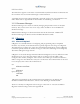
LMU Users Guide Truck Ignition Power Power Ignition Truck Battery LMU-4100 Trailer Battery LMU-1000 Input 3 Input 2 Input 2 Input 1 Ground Ground Input 1 Truck/Trailer Connector Load Sensor Unload Sensor 14.2.4 LMU Setup – Development – LMU 4100™ 14.2.4.1 Setting up the Inbound Address We are once again going to assume we have an LM Direct server at our hosting center using the IP address of 172.90.80.241.
LMU Users Guide Inputs 1 and 2 are connected to the Load and Unload sensors, which switch between High and Low signals so while the trailer is connected, the bias isn’t terribly important (i.e. we do not need to deal with the open circuit case). We do, however, want to make sure the Inputs register as closed works when the truck is disconnected. This will ensure we do not get any false safety violations alerts. For this reason we will want the Inputs to be normally low. That is, the hatches are closed.
LMU Users Guide 14.3 LMU Programming – Taxi System 14.3.1 Project Overview The final project we are going to look at is for the Hagensville Cab Company. The Hagensville Cab Company is a small organization with approximately 20 vehicles and, as of late, has been losing business to larger fleets. The owners are hoping that by adding a GPS device they can improve their efficiency and add a couple of services their competitors do not offer.
LMU Users Guide For the MDT we will need the following messages: • • • • • Cab Available (Driver –> Dispatch) Request Pickup, includes address (Dispatch -> Driver) Cab in use (Driver -> Dispatch) Cancel Pickup (Dispatch -> Driver) At pickup (Driver -> Dispatch) For the driver messages, each will be assigned to a particular button on the MDT. The incoming messages will be shown on the four line display.
LMU Users Guide As far as the LMU’s setup goes, we need to know the follow about the application: • • Messaging occurs at 19200 BAUD, 8 Data Bits, No Parity and 1 Stop Bits. Every Message is terminated by a Line Feed character (0x0A) For our credit card reader we will be using some measure of Point of Sale Terminal 26. The terminal itself would need a serial connection and a printer to meet our needs. For this example we will assume that the serial port settings are the same as the Net955.
LMU Users Guide various messages stored so we can create activity reports on the back end later. For the disposition we will therefore use Send/Log. ATS137=1 Once the type of message is selected, our next step is to determine the User Messaging mode, that is, do we need to support Long Message mode. Given the messages we’re sending fit well within the 802 byte limit on User Messages, we can keep things in standard mode, giving: ATS130=1 Next we need to setup the serial connection.
LMU Users Guide 14.3.4.3 Configuring the Aux Port The setup of our Aux Port takes a similar series of steps as the Host Port since the Point of Sale Terminal is a serial device. The only main different is that we will be focusing on SRegisters 160 through 169 Our starting point is again the mode of the Aux Port. The Aux Port doesn’t support long message mode, but it does support NMEA output.
LMU Users Guide With the two serial ports set up and the Inbound Address programmed, this should complete the LMU configuration with the exception of the PEG Script. Again, that set up for this example is described in the PEG Programming Guide. V1.0.
LMU Users Guide Appendix A — Parameter Definitions The follow table describes all parameters supported across the various LMU platforms. The second table of this appendix details which devices support which parameters. Name ID Value Index Range Data Description 0..0 Data Size (bytes) 0 Last Parameter 0 General Config Parameters Access Enables 1280 0..0 2 Accumulator Value GPS Lost Timeout 2560 1027 0..15 0..0 4 4 GPS Last Known Timeout 1028 0..0 4 Input Wake-Up Monitor 1029 0..
LMU Users Guide Name ID Value Index Range Maintenance Message Configuration 2312 0..0 Data Size (bytes) 2 Data Description 16-bit unsigned int Bit 7 – Bit 4 = Message Format 0 = Automatic based on Inbound 1 = LM Direct ID report 2 = LM eXchange ID report Bit 3 – Bit 0 = Update Times 0 = No Maintenance Updates 1 = Initial Comm Acquired OR Expired Maintenance Interval 2 = Every Comm Acquired OR Expired Maintenance Interval MDT Enables 1026 0..0 2 Mobile ID : MIN (Phone Number) 2305 0..
LMU Users Guide Name ID Value Index Range Inbound IP Address List 768 0..3 Data Size (bytes) 4 Inbound Port List 769 0..3 2 Inbound Retry Schedule 771 0..5 1 Local UDP Port 774 0..0 2 Log Retry Timer (Ignition On) 1031 0..0 4 Log Retry Attempts (Ignition On) 1032 0..0 1 Log Retry Timer (Ignition Off) 1033 0..0 4 Log Retry Attempts (Ignition Off) 1034 0..0 1 Maintenance URL 2320 0..0 64 Maintenance Message Inbound IP Address 2310 0..
LMU Users Guide Name ID Value Index Range Accumulator Reporting – Accumulator Count by Event Code 770 0..7 Data Size (bytes) 2 Inbound Event Report Contents 772 0..0 4 Logged Event Report Contents Comm Config Parameters Packet Dial String 773 0..0 4 2316 0..1 16 Packet Dial String – Current Index 2317 0..0 1 PRL Dial String 2318 0..0 16 0 bytes (ASCII chars) + null byte Dial strings used to download any PRL updates from the wireless network Modem Password (CDMA SPC) 1284 0..
LMU Users Guide Name ID Value Index Range GPRS Context – Current Index 2307 0..0 Data Size (bytes) 1 Modem SIM PIN 1285 0..0 4 Network Discriminant – Condition 1537 0..3 1 Network Discriminant – Value 1538 0..3 2 Network Discriminant – Type 1536 0..3 1 Network Side Preference (CDPD Only) 1539 0..0 1 Network Sleep Settings (CDPD Only) 1540 0..0 1 Network Username 2314 0..1 64 Network Password 2315 0..1 16 Caller ID String 2323 0..0 16 2048 0..
LMU Users Guide Name ID Value Index Range Data Size (bytes) LMU TAIP Listening Port 2051 0..0 2 TAIP Message Selection 2049 0..0 2 TAIP Remote IP Address 2052 0..0 4 TAIP Remote Port 2053 0..0 2 TAIP Vehicle ID 2050 0..3 1 PEG Parameters Acceleration Sample Count Acceleration Threshold Accumulator Threshold A/D Threshold Day of Week 278 277 266 276 269 0..3 0..3 0..15 0..3 0..3 1 4 4 2 2 Environment Mask 273 0..7 8 V1.0.
LMU Users Guide Name ID Value Index Range Data Size (bytes) Input Trigger Controls – Debounce Timer Input Trigger Controls – Delay Input High Timer 270 0..5 1 271 0..5 1 Input Trigger Controls – Delay Input Low Timer 272 0..5 1 Input Equate 256 0..3 1 PEG Enables 1037 0..0 4 Speed Trigger Controls – Speed Threshold Speed Trigger Controls – Debounce Timer 257 0..3 2 258 0..3 1 V1.0.
LMU Users Guide Name ID Value Index Range Speed Trigger Controls – Delay Speed Above Timer 260 0..3 Data Size (bytes) 1 Speed Trigger Controls – Delay Speed Below Timer 259 0..3 1 Text String - Long 2176 0..7 64 Text String – Short 2177 0..15 16 Time-Distance Profile – Time Elapsed 262 0..3 4 Time-Distance Profile – Distance Traveled 263 0..3 4 Time-Distance Profile – Heading Change 264 0..3 1 Time-Distance Profile – Minimum Time Interval 275 0..3 4 Timer Timeout 265 0..
LMU Users Guide Name ID Value Index Range Data Size (bytes) Data Description will attempt to connect to. Bluetooth PIN 2081 V1.0.6 Copyright ©CalAmp DataCom Inc 2009 0..0 4 32 bit unsigned int. The PIN value remote devices must use when connecting to the LMU’s Bluetooth adapter.
LMU Users Guide For the purposes of Parameters, there are effectively 4 different platforms, the LMU-4100, the LMU-2500, the LMU-1000/1500 and the 8-Bit products (MTU-100, LMU-900, LMU1100 and LMU-1200). The follow table describes which Parameters are available to each device type. The entry in the device column can take one of three values: • X – Indicates that all released firmware versions for the device support the parameter and the referenced index range. • 0.0.
LMU Users Guide Name ID Value Index Range Log Retry Timer (Ignition On) Log Retry Attempts (Ignition On) Log Retry Timer (Ignition Off) Log Retry Attempts (Ignition Off) Maintenance URL Maintenance Message Inbound IP Address Maintenance Message Inbound Port Maintenance Message Interval SMS Inbound Address 1031 0..0 1032 0..0 1033 0..0 1034 0..0 2320 2310 0..0 0..0 2311 0..0 2322 0..0 2321 0..0 1282 0..3 1281 1283 0..3 0..0 770 0..7 772 0..0 773 0..0 2316 2317 0..1 0..
LMU Users Guide 8-Bit LMU1000™ LMU2500™ LMU4100™ X X 27 X X X X X X X X X X Name ID Value Index Range GPRS Context String 2306 0..1 GPRS Context – Current Index Modem SIM PIN 2307 0..1 1285 0..0 Network Discriminant – Condition Network Discriminant – Value Network Discriminant – Type Network Side Preference (CDPD Only) Network Sleep Settings (CDPD Only) 1537 0..3 1538 0..3 1536 0..3 1539 0..3 1540 0..0 Network Username 2314 0..1 Network Password 2315 0..
LMU Users Guide Name ID Value Index Range Input Trigger Controls – Delay Input Low Timer Input Equate 272 0..7 256 0..0 PEG Enables 1037 0..0 Speed Trigger Controls – Speed Threshold Speed Trigger Controls – Debounce Timer Speed Trigger Controls – Delay Speed Above Timer Speed Trigger Controls – Delay Speed Below Timer Text String - Long 257 0..3 258 0..3 260 0..3 259 0..3 2176 0..7 Text String – Short 2177 0..
LMU Users Guide Appendix B — S-Register Settings For the purposes of S-Registers, there are effectively 4 different platforms, the LMU4100™, the LMU-2500™, the LMU-1000™ and the 8-Bit products (MTU-100™, LMU900™, LMU-1100™ and LMU-1200™). The follow table describes the functionality of the available S-Registers and which devices they apply to. V1.0.
LMU Users Guide 121 122 Reserved V1.0.6 Copyright ©CalAmp DataCom Inc 2009 - 136 - LMU-4100™ TetheredLocator Drivers 128 – Generic 19200 BAUD, ATDT 0, No Status 129 – CDPD – Novatel Wireless NRM 6812 Series, 19200 BAUD ,AT\\ASLIP, MSCI Status 130 – CDPD – Novatel Wireless Expedite Series, 19200 BAUD ,AT\\APPP, MSCI Status 131 – iDEN - Motorola iDEN devices, 38400 BAUD, ATD0, RALP Status 132 – CDPD – Sierra Wireless MP200, 19200 BAUD, ATD0, No Status 133 – GSM/GPRS – WaveCom, 57600 BAUD, ATDT*99***#1,
LMU Users Guide V1.0.6 Copyright ©CalAmp DataCom Inc 2009 - 137 - LMU-4100™ PPP Debug Level Description: This S-Register sets the PPP debug levels used by the LMU. All debug messages are sent to the host port. This S-Register should only be used when directed by CalAmp personnel.
LMU Users Guide V1.0.6 Copyright ©CalAmp DataCom Inc 2009 - 138 - LMU-4100™ Debug Enables Description: This S-Register sets the debug levels used by the LMU. All debug messages are sent to the host port. This S-Register should only be used when directed by CalAmp personnel.
LMU Users Guide V1.0.6 Copyright ©CalAmp DataCom Inc 2009 - 139 - LMU-4100™ Debug Enable Description: This S-Register sets debug messaging levels used by the LMU. All debug messages are sent to the host port. This S-Register should only be used when directed by CalAmp personnel.
LMU Users Guide V1.0.6 Copyright ©CalAmp DataCom Inc 2009 - 140 - LMU-4100™ GPS Debug Enables Description: This S-Register sets debug messaging levels used by the LMU in regards to GPS. All debug messages are sent to the host port. This S-Register should only be used when directed by CalAmp personnel.
LMU Users Guide V1.0.6 Copyright ©CalAmp DataCom Inc 2009 - 141 - LMU-4100™ Environment Restore Description: The environment restore function allows the LMU to save certain items into non-volatile memory. These items will be restored on the next power up.
LMU Users Guide 129 130 131 Comm Disconnect Count Description: This S-Register will control the number of Comm Disconnects the LMU must receive before switching GPRS Context Settings. Settings: 0-255 Comm Disconnects (0 = Off) Serial Port Mode Control Description: This S-Register controls what mode the LMU’s MDT Port is in.
LMU Users Guide 133 134 135 Serial Port Misc.
LMU Users Guide 137 138 GSD(User) Message Disposition Description: This S-Register controls the Disposition of the User Message. Settings: 1 = Send Message, Log if Send Fails 2 = Send Message, Log if Send Fails 3 = Log Message 4 = Priority Message 5 = Unacknowledged Message 7 = Route Incoming (Client to LMU) SMS messages to the host serial port. Route all User Messages to the SMS Destination Address 8 = Route Incoming (Client to LMU) SMS messages to the host serial port.
LMU Users Guide V1.0.
LMU Users Guide V1.0.6 Copyright ©CalAmp DataCom Inc 2009 - 146 - LMU-4100™ Unit Configuration Controls Description: This S-Register controls some of the advanced settings of the LMU’s Settings: Bit 0 – A/D Scaling Set = Forces the A/D to use a 38.
LMU Users Guide 142 143 144 Horizontal Position Accuracy Threshold Description: This value is used to help control the position used while the LMU is ‘pinning’. The GPS accuracy estimate must be lower than this value for the LMU’s position value to be updated. Settings: The accuracy limit to use, ranging from 1 to 255 meters. 0 Will disable this feature. Configuration Version Description: This S-Register is reserved for use by the customer to Identify the Configuration Version seen in PULS.
LMU Users Guide 146 147 LMU-4100™ Mobile ID Type Selection Description: This value specifies with mobile ID Type to use in the Options header of all Inbound messages.
LMU Users Guide 149 150 Send-Fail Modem Restart Count Threshold Description: If the LMU is unable to send a message the number of times in this S-register, it will reset the wireless modem Settings: The number of Send Fails to wait before resetting the wireless modem ranging from 1 to 255. 0 disables this feature. Alternate Modem Select Description: This S-Register controls which modem driver the LMU uses to connect to a wireless device when using Comm Index 1.
LMU Users Guide 151 Reserved 152 LCP Echo Interval Description: This S-Register dictates how often the LMU will send an LCP Echo request to the wireless modem. If the modem does not respond 3 times in a row, the modem is reset. This does not apply to CDMA devices. Settings: The number of Send Fails to wait before resetting the wireless modem ranging from 1 to 255 second. 0 disables this feature. V1.0.
LMU Users Guide 154 155 X X KMIP and Connection Monitor Control Register Description: This S-Register controls the advanced KMIP settings and Connection Monitor Settings of the LMU.
LMU Users Guide 157 V1.0.6 Copyright ©CalAmp DataCom Inc 2009 - 152 - LMU-4100™ Position Update Controls Description: This S-Register controls the advanced GPS behavior settings of the LMU.
LMU Users Guide 159 GPIO Function Selection Description: This S-Register controls setup of the GPIO (General Purpose Input/Output) lines on the LMU and IOPod. Settings: Bit 0 – GPIO 1 Function Set = Configure GPIO 1 to be an output. Input function disabled Cleared = Configure GPIO1 to be and input Bit 1 – GPIO 2 Function Set = Configure GPIO 2 to an output. Input function disabled Cleared = Configure GPIO 2 to be an input V1.0.
LMU Users Guide 161 162 Aux Serial Port Baud Rate Description: This S-Register will set the LMU’s Host Port Baud rate while not in Standard mode Settings: 4 = 4800 5 = 9600 7 = 19200 9 = 38400 10 = 57600 12 = 115200 Aux Serial Port Word Definition (Parity, Stop Bits, Word Size) Description: This S-Register will set the LMU’s Host Port word definition while not in Standard mode Settings: Bit 0 – Bit 1 – Word Size 0 = 5 bits 1 = 6 bits 2 = 7 bits 3 = 8 bits Bit 2 – Stop Bits Set = 2 Stop Bits Cleared = 1 S
LMU Users Guide 164 165 166 Aux Serial Port GSD(User) Message Termination Character Description: This S-Register will set the Termination Character to be used to end a user message Settings: Decimal value of the ASCII Character ranging from 0 -255. Aux Serial Port GSD(User) Message Termination Length Description: This S-Register controls the maximum length of a User Message. Settings: The size of the user message ranging from 4 to 804 bytes.
LMU Users Guide 168 169 Aux Serial Port GSD Termination Timeout Description: This S-Register controls the length of time the LMU will wait for a User Message to either receive the termination character or reach the max termination length. If this time elapsed and there is data, a User Message is sent Settings: The length of time in milliseconds the LMU will wait ranging from 1 to 255ms.
LMU Users Guide V1.0.6 Copyright ©CalAmp DataCom Inc 2009 - 157 - LMU-4100™ BlueLocator Configuration Settings Description: This S-Register controls the settings of the BlueLocator’s Bluetooth Adapter (BTA).
LMU Users Guide 172 PDP Context Timeout Description: This S-Register controls the length of time the LMU will wait after the last data active before resetting the PDP Context session modem. Settings: The length of time to wait ranging from 1 to 255 minutes. 0 disables this feature. V1.0.6 Copyright ©CalAmp DataCom Inc 2009 - 158 - LMU-4100™ Unit Configuration Settings Description: This S-Register controls some of the advanced configuration settings of the LMU.
LMU Users Guide 174 175 V1.0.6 Copyright ©CalAmp DataCom Inc 2009 - 159 - LMU-4100™ Serial Message Configuration Description: This S-Register controls the serial message settings for use with the Serial Message PEG Action. The control is split into two parts, the protocol (bits 0-4) and the port (bits 5-7).
LMU Users Guide V1.0.6 Copyright ©CalAmp DataCom Inc 2009 - 160 - X LMU-4100™ Motion Detect Filter – Duration Description: This S-Register controls the minimum length of time the LMU uses to detect motion. (i.e. the LMU must be moving for at least S176S). Settings: The minimum length of time the LMU must be moving to detect movement with its motion sensor. The field uses a 10ms LSB so a value of 67 = 670mS.
LMU Users Guide Appendix C — ASCII Chart Hexadecimal to ASCII 0 1 2 3 4 5 6 7 0 NU L DL E SP 0 @ P ` p 1 SO H DC 1 ! 1 A Q a q 2 ST X DC 2 “ 2 B R b r 3 ET X DC 3 # 3 C S c s 4 EO T DC 4 $ 4 D T d t 5 EN Q NA K % 5 E U e u 6 AC K SY N & 6 F V f v 7 BE L ET B ‘ 7 G W g w 8 BS 9 HT A LF B VT C FF D CR E SO F SI CA N ( 8 H X h x EM SU B * : J Z j z ES C + ; K [ k { FS GS RS US , < L \ l | = M ] m } .
LMU Users Guide Appendix D – HyperTerminal Setup Click the Start button and go to Programs, Accessories and Communications. Click the Hyper Terminal icon. This should display a new connection wizard. Name the connection LMU Click OK. V1.0.
LMU Users Guide Change Connect using field to read Direct to ComX, where X is the Com port that the LMU is attached to. Click OK. Change Bits per second to read 115200. Click OK. V1.0.
LMU Users Guide The wizard should now close and a cursor should appear in the main HyperTerminal window. It is a good idea to verify that communications are established with the LMU. This can be done by issuing the following AT Command: ATI0 A response similar to the following should appear: APP:LMU,001 V8.0b (Sep 26 2007 18:10:32) PIC:TIM S/N 4130000200 GPS:UBLOX-00040001 -5.00 Jan 09 2006 12:00:00 Radio:SIEMENS TC65-REVISION 02.
LMU Users Guide Appendix E - Windows Vista – Putty Setup Microsoft stopped including the HyperTerminal program as part of its offering with Windows Vista. As a result you will need to find an alternate program to communicate directly with the LMU. One option is to purchase HyperTerminal from Hilgraeve (http://www.hilgraeve.com/hyperterminal.html). Alternatively you can use a terminal emulation program such as PuTTY. (http://www.chiark.greenend.org.uk/~sgtatham/putty/).
LMU Users Guide 9. To test the connection, enter the AT Command ATI0. (Note, if you cannot see what you are typing, enter a second AT Command of ATE1 10. You should see a response similar to the following: V1.0.
LMU Users Guide Logging data to file with PuTTY To start capturing LMU responses to file you can use the logging setup in PuTTY. This is done as follows: 1. Launch the PuTTY.exe file 2. From the Saved Sessions list select CalAmp LMU and click Load 3. From the Category list expand Session and click Logging 4. Under Session logging select All session output 5. For Log file name enter \ LMU_Debug_&Y_&M_&D_&T.txt where is a know good directory path. (For example C:\Temp\) V1.
LMU Users Guide 6. Under Categories select Session 7. Click Save This will create a file called LMU_Debug_YYYY_MM_DD_HH:MM:SS.txt every time you open the session where YYYY is the current year, MM is the current month, DD is the current day and HH:MM:SS is the current time. V1.0.
LMU Users Guide Appendix F - Pairing to the LMU-4100 Using Windows Mobile To pair the LMU-4100™ using a BTA with a Windows Mobile device you would perform the following steps: 1. Go to Start -> Settings and click the Connections tab. 2. Tap the Bluetooth icon. 3. In the Mode tab, check both the Turn on Bluetooth and Make this device discoverable to other devices options. 4. Under devices, delete any existing connections 5. Tap New Partnership... 6. Select LMU xx.xx.xx from the list that appears.
LMU Users Guide Appendix G - Adding a Modem Driver In order to use the LMU-4100™ as a modem you may need to add a new modem driver so that your operating system will recognize it as a valid device. The following sections describe how to do this on a common laptop based operating system and a common PDA operating system. You may need to refer to your operating system’s documentation for further details.
LMU Users Guide 5. Click the Continue button 6. Check the Don’t detect my modem; I will select it from a list option and click the Next > button. 7. Under Manufacturer select (Standard Modem Types) 8. Under Models select Standard 19200 bps Modem V1.0.
LMU Users Guide 9. Click Next >. 10. Click the Selected Ports option and then choose the COM Port the LMU-4100 is connected to. If you are plugged into the back of your laptop, this will generally be COM 1. If you are using a USB to Serial Adapter or a Bluetooth device with a Serial Port Profile it will likely be COM 5 or higher. In the example below, the USB to Serial adapter is on COM3: V1.0.
LMU Users Guide 11. Click Next >. 12. When you see that the modem installation has been successful, click Finish V1.0.
LMU Users Guide 13. From here you will need to set the Maximum Port speed to 115200 BAUD for use with the LMU-4100. To do this, highlight the Standard 19200 bps modem and click Properties. V1.0.
LMU Users Guide 14. 15. 16. 17. Click the Change Settings button. Click the Continue button. Click the Modem tab. Change the Maximum Port Speed value to be 115200. V1.0.
LMU Users Guide 18. Click OK to exit back to the main control panel. 19. Click OK to finish. V1.0.
LMU Users Guide Windows XP This set of instructions assumes you are using the ‘Classic’ view of the Control Panel. 20. Go to Start, Settings, and click Control Panel. 21. Open the Phone and Modem Options control. 22. Click the Modems tab. 23. Click the Add… button V1.0.
LMU Users Guide 24. Check the Don’t detect my modem; I will select it from a list option and click the Next > button. 25. Under Manufacturer select (Standard Modem Types) 26. Under Models select Standard 19200 bps Modem V1.0.
LMU Users Guide 27. Click Next >. 28. Click the Selected Ports option and then choose the COM Port the LMU-4100™ is connected to. If you are plugged into the back of your laptop, this will generally be COM 1. If you are using a USB to Serial Adapter or a Bluetooth device with a Serial Port Profile it will likely be COM 5 or higher. 29. Click Next >. V1.0.
LMU Users Guide 30. When you see that the modem installation has been successful, click Finish 31. In some cases it may be necessary to change the default BAUD rate associated with the modem. Specifically, it should match the Host Port BAUD rate of the LMU- V1.0.
LMU Users Guide 4100. To do this, highlight the Standard 19200 bps modem and click Properties. 32. Click the Modem tab. V1.0.
LMU Users Guide 33. Change the BAUD rate using the Maximum Port Speed pull-down list. 34. Click OK to exit back to the main control panel. 35. Click OK to finish. V1.0.
LMU Users Guide Windows Mobile 5.0 Adding a modem into Windows Mobile devices is a little trickier than for a laptop based operating system. Specifically you will need to make an adjustment to the Registry of your Windows Mobile device. You will need to make the following additions: [HKEY_LOCAL_MACHINE\ExtModems\CalAmpLMU] "Port"="COM0:" "FriendlyName"="CalAmp LMU" "DeviceType"=dword:00000001 [HKEY_LOCAL_MACHINE\ExtModems\CalAmpLMU\Settings] [HKEY_LOCAL_MACHINE\ExtModems\CalAmpLMU\Init] Note that the ‘Port
LMU Users Guide Appendix H – Creating a Dial-Up Networking Session Windows Vista 1. Go to Start, Settings and click Control Panel. 2. Double click the Network and Sharing Center icon. 3. Under Tasks select Setup a connection or network 4. From the list, choose Setup a dial-up connection and Click Next V1.0.
LMU Users Guide 5. 6. 7. 8. In the Dial-up phone number field enter 0 For User name use dummy For the Password also use dummy For Connection name use CalAmp LMU V1.0.
LMU Users Guide 9. Make sure your LMU is powered on and plugged into the appropriate COM port then click Connect V1.0.
LMU Users Guide V1.0.
LMU Users Guide If the connection fails you may need to edit the Dial-Up Networking connection’s properties. This can be done as follows 1. Go to Start, Settings and click Control Panel. 2. Double click the Network and Sharing Center icon. 3. Under Tasks select Manage network connections 4. Double click the CalAmp LMU icon 5. Click the Properties button V1.0.
LMU Users Guide 6. Click Continue 7. Make sure the Connect using field reads a Modem – Standard 19200 bps Modem (COM) 8. Make sure the Phone number is set to 0 V1.0.
LMU Users Guide 9. Click Configure… 10. Make sure Maximum speed (bps) is set to 115200 11. Click OK to exit the Modem Configuration window 12. Click OK again to exit the CalAmp LMU Properties window V1.0.
LMU Users Guide 13. Make sure the CalAmp LMU is powered on and connected to the appropriate COM port and click Dial Verify the connection by hovering the mouse over the networking icon in the task tray. V1.0.
LMU Users Guide Windows XP 10. Go to Start, Settings and click Control Panel. 11. Double click the Network Connections icon. 12. Under Network Tasks select Create a new connection. 13. Click Next > V1.0.
LMU Users Guide 14. Select Connect to the Internet 15. Click Next > 16. Select Set up my connection manually 17. Click Next > V1.0.
LMU Users Guide 18. Select Connect using a dial-up modem 19. Click Next > 20. Select Standard 19200 bps Modem making sure to de-select any other options. 21. Click Next > V1.0.
LMU Users Guide 22. Name the connection CalAmp LMU 23. Click Next > 24. Set the Phone Number to 0. 25. Click Next > V1.0.
LMU Users Guide 26. Enable the connection for anyone’s use. 27. Click Next > 28. Enter ‘dummy’ for both the Username and Password. 29. Uncheck the ‘Use this account name and password when anyone connects to the Internet from this computer’ option. V1.0.
LMU Users Guide 30. Uncheck the ‘Make this the default internet connection’ option. 31. Click Next > V1.0.
LMU Users Guide 32. Click Finish V1.0.
LMU Users Guide 33. Click Properties 34. Click Configure 35. Change the Maximum Speed (bps) to match the BAUD rate you selected when you created the Standard 19200 bps Modem. 36. Click OK 37. Click OK 38. Make sure the LMU-4100 is connected to the appropriate COM port, is powered on and is registered to the wireless network. 39. Click Dial You should now be connected to the Internet via the LMU. V1.0.
LMU Users Guide Windows Mobile 1. 2. 3. 4. 5. 6. 7. 8. 9. 10. 11. Go to Start -> Settings and click the Connections tab. Tap the Add a new modem connection link. Name the connection LMU Under Select a modem choose CalAmp LMU(i.e. the same modem driver you created above) Tap Next For the phone number use 0 and tap Next You don't need to bother with a Username, Password or Domain. Click Advanced. If you are using a direct serial connection, make sure the Baud rate matches what you're using on the LMU (e.g.