
Installation guide

LMU Users Guide
V1.0.6 December 10 2009
Copyright ©CalAmp DataCom Inc 2009
- 153 - CalAmp Proprietary & Confidential
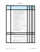
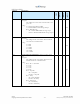
Register
Description
8-Bit
LMU-1000™
LMU-2500™
LMU-4100™
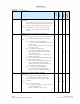
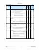
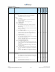
158
Input Bias Configuration
Description:
This S-Register controls setup of the inputs on the
LMU and IOPod.
Settings:
Bit 1 – GPIO1 – Input Bias
- Set = High (Vcc) Bias)
- Cleared = Low (Gnd) Bias)
Bit 2 – GPIO2 – Input Bias
- Set = High (Vcc) Bias)
- Cleared = Low (Gnd) Bias)
Bit 3 – Input 3 – Input Bias
- Set = High (Vcc) Bias)
- Cleared = Low (Gnd) Bias)
Bit 4 – Input 4 – Input Bias
- Set = High (Vcc) Bias)
- Cleared = Low (Gnd) Bias)
Bit 5 – Input 5 – Input Bias
- Set = High (Vcc) Bias)
- Cleared = Low (Gnd) Bias)
Bit 6 – Input 6 – Input Bias
- Set = High (Vcc) Bias)
- Cleared = Low (Gnd) Bias)
Bit 7 – Input 7 – Input Bias
- Set = High (Vcc) Bias)
- Cleared = Low (Gnd) Bias)
X X X X
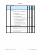
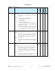
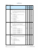
159
GPIO Function Selection
Description:
This S-Register controls setup of the GPIO (General
Purpose Input/Output) lines on the LMU and
IOPod.
Settings:
Bit 0 – GPIO 1 Function
- Set = Configure GPIO 1 to be an output. Input
function disabled
- Cleared = Configure GPIO1 to be and input
Bit 1 – GPIO 2 Function
- Set = Configure GPIO 2 to an output. Input
function disabled
- Cleared = Configure GPIO 2 to be an input
X X