
Installation guide

LMU Users Guide
V1.0.6 December 10 2009
Copyright ©CalAmp DataCom Inc 2009
- 158 - CalAmp Proprietary & Confidential
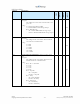
Register
Description
8-Bit
LMU-1000™
LMU-2500™
LMU-4100™
171
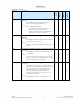
Unit Configuration Settings
Description:
This S-Register controls some of the advanced
configuration settings of the LMU.
Settings:
Bit 0 – 1-Bit Bus
- Set = Enables 1 Bit Bus operations but disables
Output-0 controls
- Cleared = disables 1 Bit Bus operations.
Bit 1 – RESERVED
Bit 2 – Radio Sleep
- Set = The LMU will leave the modem on when it
goes to sleep to allow the LMU to wake up via an
SMS message
- Cleared = The modem will be powered off when the
LMU goes to sleep
Bit 3 – LED Blink Controls
- Set = LEDs will blink according to the Input Code
pattern instead of the Comm and GPS patterns
- Cleared = LEDs will blink according to the Comm
and GPS patterns
Bit 4 – AT Command Password Protection
- Set = The LMU will only respond to AT Commands
if a password is entered first.
- Cleared = The LMU will respond to AT Command
without entering a password
Bit 5 – LED Alternate Blink Code
- Set = LEDs will blink according to the Input Code
pattern instead of the Comm and GPS patterns if Bit
3 is also set
- Cleared = LEDs will blink according to the Comm
and GPS patterns
Bit 6 – 1 Bit Bus Temperature Sensor (LMU-2500 Only)
- Set = The 1 Bit Bus is configured for a temperature
sensor.
- Cleared = The 1-Bit Bus is configured for an ID tag
X X 1.0j X
172
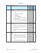
PDP Context Timeout
Description:
This S-Register controls the length of time the LMU
will wait after the last data active before resetting the
PDP Context session modem.
Settings:
The length of time to wait ranging from 1 to 255
minutes. 0 disables this feature.
X X X X